4 alarm configurable parameters, Figure 7-13. alarm parameter configuration window – Micromod Micro-DCI: 53MT6000 Micro-Tools User Manual
Page 75
53MT6000 INSTRUCTION MANUAL
Database Editor 59
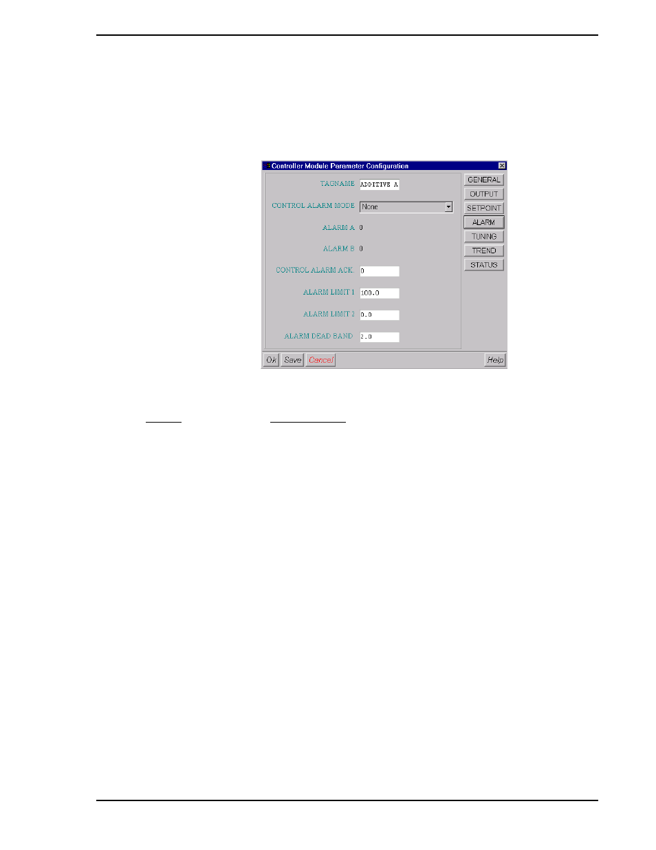
7.4.7.4 ALARM Configurable Parameters
The control module ALARM parameters can be configured by clicking on the ALARM button. The window
shown in
will be displayed. The database locations where these values are stored for CON0
are shown in brackets [ ].
Figure 7-13. Alarm Parameter Configuration Window
ENTRY
EXPLANATION
Tagname:
Tagname of the CON module [A00].
Control Alarm Mode:
This parameter is used to select the control module Alarm mode
[B335]. Available selections:
None
PA1:HI
PA2:LO
PA1:HI PA2:HI-HI
PA1:LO PA2:LO-LO
PA1:HI-DEV PA2:LO-DEV
PA1:HI PA2:LO
Alarm A:
Alarm status for the selected alarm limit 1 [L110].
Alarm B:
Alarm status for the selected alarm limit 2 [L111].
Control Alarm Ack:
This database parameter is used to acknowledge the control
module alarms.
Alarm Limit 1:
Alarm Limit value 1 [C103].
Alarm Limit 2:
Alarm Limit value 2 [C104].
Alarm Dead Band:
Defines a value below the high limit and above the low limit through
which the process measurement must travel before it will reset the
alarm condition. This is also known as hysteresis. [C105]
OK:
Saves changes, closes window and returns to main menu.