4 sub-menu descriptions, 1 ani menu, Figure 7-4. ani parameter configuration window – Micromod Micro-DCI: 53MT6000 Micro-Tools User Manual
Page 61: D in, Section 7.4
53MT6000 INSTRUCTION MANUAL
Database Editor 45
7.4 Sub-Menu Descriptions
The following sections describe the module windows displayed when each item is selected from the main
database editor window. For details concerning any of the parameters, see the Modular Controller Instruc-
tion Bulletin. Note that not all values are configurable; these are identified as "display only".
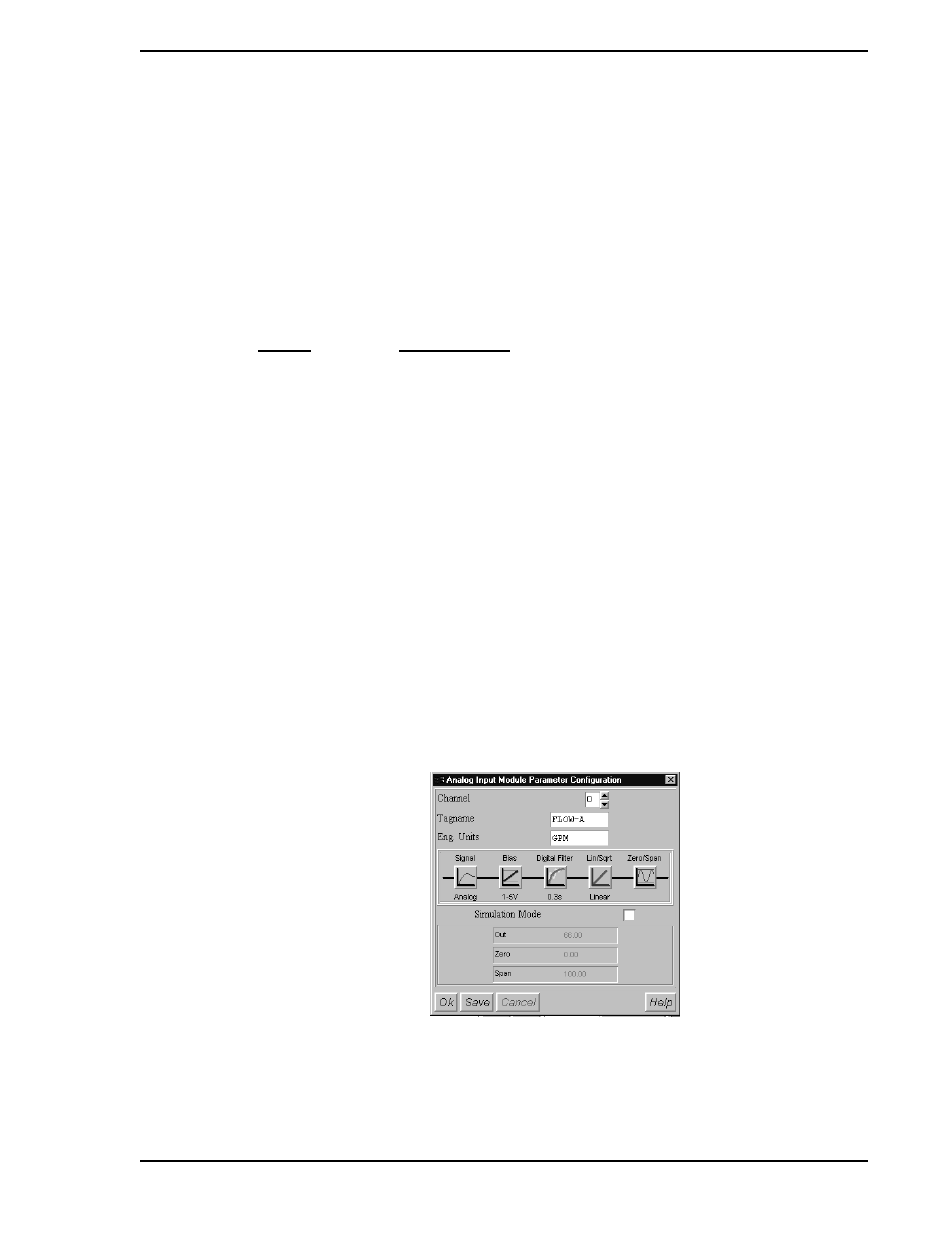
7.4.1 ANI Menu
The number of analog inputs per controller is dependent on the options purchased with the controller.
MicroTools provides access for all nine possible analog input modules (AI0 through AI8). The window for
each AI module contains the entries listed below.
In the unlikely event that the calibration span and zero must be changed, see
for a descrip-
tion of adjusting calibration constants using the CALIBRATION menu.
ENTRY
EXPLANATION
Channel:
Displays channel number
Tagname:
Tagname
Eng. Unit:
Engineering Unit
Signal:
Selects analog or frequency input (only active for Channels
4 through 7)
Bias:
1 - 5 or 0 - 5 volt
Digital Filter:
Digital filtering; 0 is no filtering
Lin/Sqrt:
Linear or Square root
Zero/Span:
Full scale range in Engineering Units
Simulation:
Allows manual modification of module output
OK:
Saves changes, closes window and returns to main menu
Save:
Saves changes without closing window
Cancel:
Cancels changes and returns to main menu
Figure 7-4. ANI Parameter Configuration Window