3 modbus master parameter configuration, Figure 7-29. modbus master configuration window – Micromod Micro-DCI: 53MT6000 Micro-Tools User Manual
Page 103
53MT6000 INSTRUCTION MANUAL
Database Editor 87
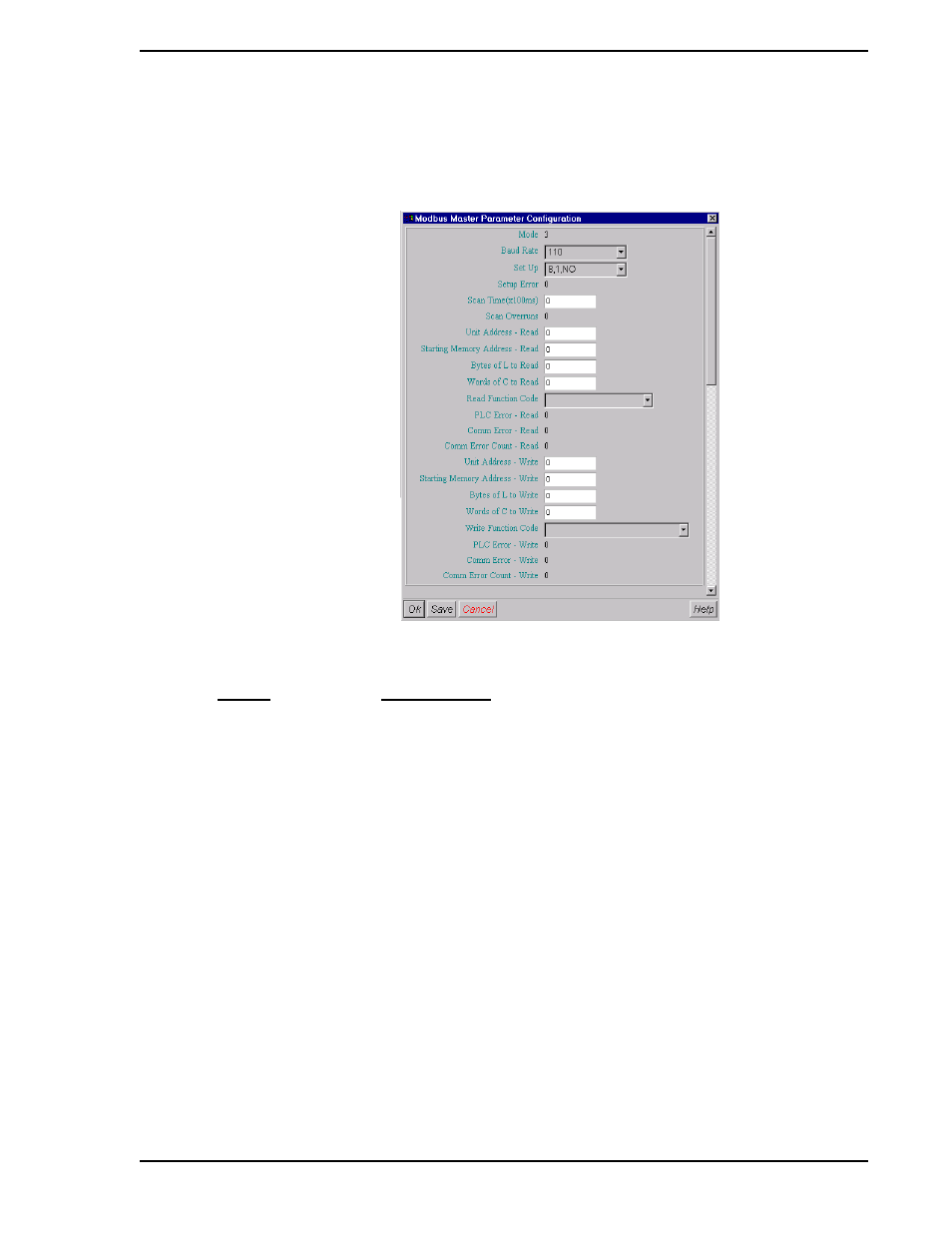
7.4.16.3 Modbus Master Parameter Configuration
Once the preferred PLC device has been selected, a separate configuration window specific to the inter-
face is displayed, as shown in
:
Figure 7-29. Modbus Master Configuration Window
ENTRY
EXPLANATION
Mode:
This displayed value represents the index number of the PLC type
[DDIA = B290, DDIB = B456]
Baud Rate:
This designates the data transfer rate. Clicking on the "down arrow"
reveals a list of 11 selections, these are [DDIA = B292, DDIB =
B458]:
110
300
600
1200
2400
4800
9600
19200
14400
28800
38400