5 single station cascade control – Micromod Micro-DCI: 53SL6000 Single Loop Controller User Manual
Page 96
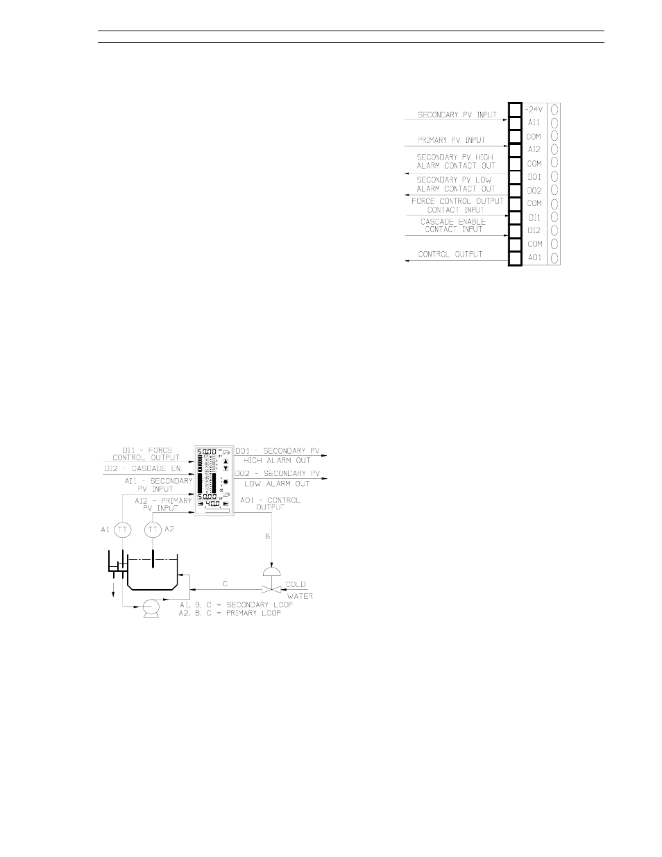
8.5 Single Station Cascade Control
A single station cascade control strategy is illus-
trated in Figure 8-10. This control strategy is imple-
mented with the controller default settings and
cASc control scheme. With single station cascade
control, two standard PID control loops function
together as a primary (loop 2) and secondary (loop
1). The output of the primary control loop, based
on its setpoint and process variable, becomes the
setpoint input to the secondary control loop. This
controller setup is suited to process applications
where the primary loop is usually slower than the
secondary loop. The cascade action overcomes
the slower process time lags of the primary loop by
providing more immediate response to changes in
the faster secondary loop, which in turn reduces
disturbances to the primary loop. Transfer be-
tween local and cascade control is bumpless be-
cause the primary control’s output is forced to
match the secondary control’s setpoint when the
secondary control is in local mode (this is indicated
by a blinking loop 2 manual LED). In the illustrated
application below, the temperature (primary vari-
able) of a liquid in a tank is maintained by regulat-
i n g c o l d w a t e r f l o w t o a d j u s t t a n k j a c k e t
temperature (secondary variable).
Figure 8-10. Single Station Cascade
Control Application
The signal connector is illustrated in Figure 8-11
and the connector pin assignment descriptions are
provided in the sections that follow. These sec-
tions also contain the applicable display prompts
that may require configuration changes.
Figure 8-11. Single Station Cascade
Signals
8.5.1 AI1 - Secondary PV Input
This is the secondary process loop analog input
signal value that is compared to the primary control
output (setpoint in) to determine the control output.
Applicable menu prompts that may require configu-
ration changes:
Section 5.2, conF-Ai.1-(SPan, ZEro, SQrt, bASE,
dFLt).
For PV alarms:
Section 7.7, conF-cn.1-(AiX, PL1, PL2, Adb).
8.5.2 AI2 - Primary PV Input
This is the primary process loop analog input signal
value that is compared to the primary control set-
point to determine the output (setpoint) value fed
into the secondary process loop.
Applicable menu prompts that may require configu-
ration changes:
Section 5.2, conF-Ai.2-(SPan, ZEro, SQrt, bASE,
dFLt).
8.5.3 DO1 - Secondary PV High
Alarm Contact Out
D01 is closed (on) when the secondary process
variable value is not within the loop 1 process
alarm limit 1 (PL1) setting.
Applicable parameter that may require configura-
tion change:
Section 5.6, ProG-do-inV1.
Section 8. Eight Control Strategies
53SL6000 Instruction Manual
8-9