4 logic blocks 1, 2, 3 & 4 – Micromod Micro-DCI: 53SL6000 Single Loop Controller User Manual
Page 57
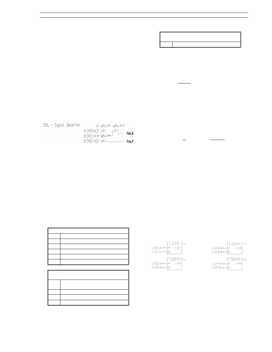
6.3.7 SEL Mode
The selector allows one of four analog input values
to be passed to the analog output based on the
values of the two digital inputs (E and F). Three of
the analog inputs (B, C, and D) can be scaled by
the constants K1 through K6. The switching dia-
gram below the equation shows how the digital
inputs control the value passed to the analog out-
put.
if E
=
1 and F
=
1, then X
=
K5D
+
K6
if E
=
1 and F
=
0, then X
=
K3C
+
K4
if E
=
0 and F
=
1, then X
=
K1B
+
K2
if E
=
0 F
=
0, then X
=
A
6.3.8 Gas Flow Compensation
Equations
Pressure and temperature compensated gas flow
equations for both linear and square root flow ele-
ments are provided to compute the mass flow or
"standard volume" flow of a gas. The equations
handle both perfect and imperfect gases. Three
inputs representing A - flow (differential pressure),
B - absolute pressure, and C - absolute tempera-
ture are converted to a flow output signal based on
a set on parameters K1 through K6.
Imperfect Gases in Operating Zone
K1
Overall meter coefficient
K2
Slope of Y factor line (negative)
K3
Coefficient in density equation
K4
Pressure bias in density equation
K5
Temperature bias in density equation
K6
Density bias in density equation
K3-K6 Inputs for Gas that Behaves as
Perfect Gas in Operating Zone
K3
Molecular weight/Universal Gas
Constant, R
K4
0
K5
460
° R or 273° K
K6
0
K2 Input if Acoustic Ratio is Very Low
(Y = 1.0)
K2
0
6.3.8.1 Linear Gas Flow Compensation
(LFLo) Equation
X
=
K1A
[
K3
B
−
K4
C
+
K5
+
K6
]
A is actual CFM volumetric flow
B is absolute pressure
C is temperature (in R or K)
6.3.8.2 Square Root Gas Flow
Compensation (SFLo) Equation
X
=
K1
[
1
−
K2
A
B
]
√
A
[
K
3
B
−
K4
C
+
K5
+
K6
]
A is measured differential pressure
B is absolute pressure
C is temperature (in R or K)
6.4 Logic Blocks 1, 2, 3, and 4
As shown in the figures below, each logic block
1,2,3, and 4 can perform a selected mode of opera-
tion on two input variables A and B to produce an
output at LG(1-4). Inputs A and B, as well as the
output, are all logic values (0/1). The applicable
modes of operation and the selectable inputs for all
four logic blocks are provided in Table 6-3 and the
outputs produced by the various operating modes
are summarized in Table 6-4.
Section 6. Signal Value Modification
53SL6000 Instruction Bulletin
6-7