4 auto/manual selector – Micromod Micro-DCI: 53SL6000 Single Loop Controller User Manual
Page 94
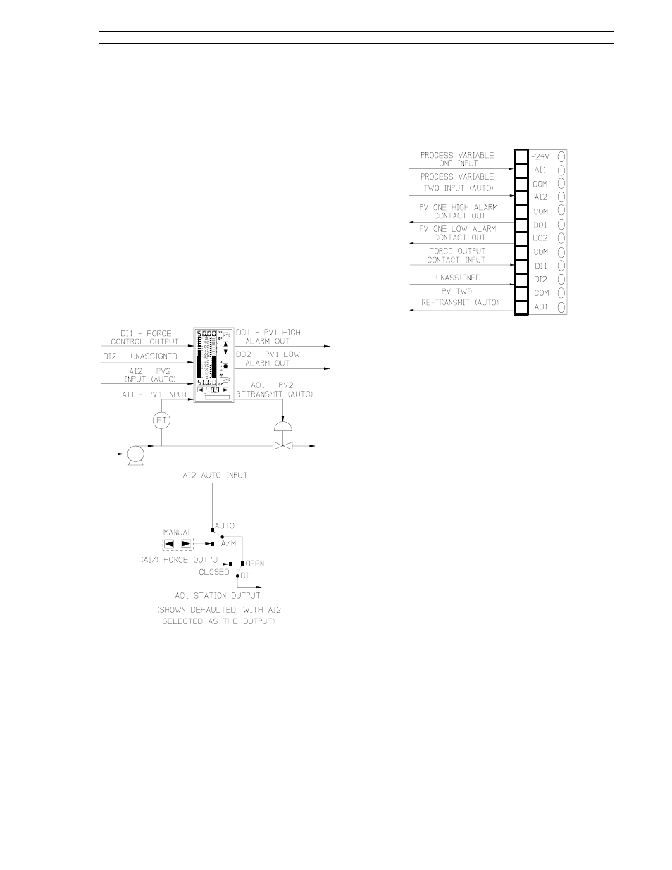
8.4 Auto/Manual Selector
An auto/manual selector application is illustrated in
Figure 8-8. This application is implemented with
the controller default settings and the in.Ld control
scheme. The auto/manual selector default settings
allow auto-throughput when Auto is selected with
the A/M push button. In automatic, the signal on
AI2 is passed through to the station’s output (AO1).
Manual operation occurs when M is selected with
the A/M push button. In manual, the station output
is controlled with the output push buttons. Transfer
from automatic to manual is bumpless. There is no
PID control performed by the automatic/manual se-
lector ; however , the station monitors AI1 for
alarmed conditions, which are signaled with DO1
and DO2. If DI1 is closed, the force output signal
appears at A01.
Figure 8-8. A/M Selector Application
The force output signal can be applied to an analog
input (e.g., universal analog input module AI3 or
AI4) from an external source, or it can be a con-
stant value entered into one of the controller analog
input registers. AI7 is shown in Figure 8-8 in pa-
renthesis to indicate the controller does not have
any optional AI inputs and that this value is a con-
stant that was entered into AI7.
The signal connector is illustrated in Figure 8-9 and
the connector pin assignment descriptions are pro-
vided in the sections that follow. These sections
also contain the applicable display prompts that
may require configuration changes.
Figure 8-9. A/M Selector Signals
8.4.1 AI1 - Process Variable 1 Input
This analog signal is the designated input variable
that is checked to be within acceptable process
limits.
Applicable parameters that may require configura-
tion changes:
Section 5.2, conF-Ai.1-(SPan, ZEro, SQrt, bASE,
dFLt).
For PV alarms:
Section 7.7, conF-cn.1-(AiX, PL1, PL2, Adb).
8.4.2 AI2 - Process Variable 2 Input
(Auto)
This analog signal is gated through as the AO1
selector output if force output is not active and auto
is selected with the A/M push button.
Applicable parameters that may require configura-
tion changes:
Section 5.2, conF-Ai.2-(SPan, ZEro, SQrt, bASE,
dFLt).
8.4.3 DO1 - PV1 High Alarm Contact
Out
D01 is closed (on) when the alarmed process vari-
able value, PV1, is not within the process alarm
limit 1 (PL1) setting.
Applicable parameter that may require configura-
tion change:
Section 5.6, ProG-do-inV1.
Section 8. Eight Control Strategies
53SL6000 Instruction Manual
8-7