3 ratio control – Micromod Micro-DCI: 53SL6000 Single Loop Controller User Manual
Page 92
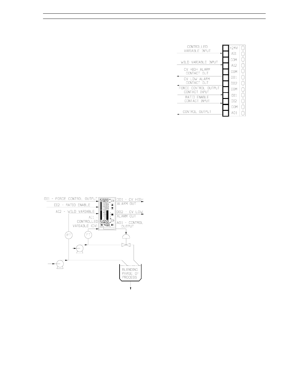
8.3 Ratio Control
Ratio control is used where one variable, called the
controlled variable, must be automatically main-
tained in definite proportion to another variable,
called the wild variable. Ratio control is imple-
mented with the controller default settings, the
SnGL control scheme, and the ratio setpoint K-SP
selected from the setpoint mode (ConF-cn.1-SPM)
parameter. A ratio control strategy is illustrated in
Figure 8-6. Field transmitters (e.g, flow meters)
must be installed in each variable line. Signals
from the controlled and wild variable transmitters
(AI1 and AI2 respectively) are received by the con-
troller which compares them and calculates the re-
quired correction that is applied as an output signal
(AO1) to a final control element (e.g., valve) in the
controlled variable line. The final element in the
controlled variable line is moved to alter line
throughput so that the predetermined ratio between
the two lines is maintained. The predetermined
ratio is set at the controller with the ratio/local (R/L)
push button in R. While in ratio control, the set-
point push buttons are used to set the desired ratio
value; when the R/L push button is in local control,
the setpoint push buttons modify only the setpoint
value. In local control, the controlled variable line
functions in single loop control mode.
Figure 8-6. Ratio Control Application
The signal connector is illustrated in Figure 8-7 and
the connector pin assignment descriptions are pro-
vided in the sections that follow. These sections
also contain the applicable display prompts that
may require configuration changes.
Figure 8-7. Ratio Control Signals
8.3.1 AI1 - Controlled Variable Input
This is the controlled line analog input signal value
that must be maintained in proportion to the wild
variable input value.
Applicable parameters that may require configura-
tion changes:
Section 5.2, conF-Ai.1-(SPan, ZEro, SQrt, bASE,
dFLt).
For CV alarms:
Section 7.7, conF-cn.1-(AiX, PL1, PL2, Adb).
8.3.2 AI2 - Wild Variable Input
This is the wild variable analog input signal value
that determines the required controlled variable in-
put as specified by the ratio setting.
Applicable parameters that may require configura-
tion changes:
Section 5.2, conF-Ai.2-(SPan, ZEro, SQrt, bASE,
dFLt).
Section 7.7, conF-cn.1-(Sh, SL, SSr, B1).
8.3.3 DO1 - Controlled Variable High
Alarm Contact Out
D01 is closed (on) when the controlled variable
value is not within the process alarm limit 1 (PL1)
setting.
Applicable parameter that may require configura-
tion change:
Section 5.6, ProG-do-inV1.
8.3.4 DO2 - Controlled Variable Low
Alarm Contact Out
D02 is closed (on) when the controlled variable
value is not within the process alarm limit 2 (PL2)
setting.
Section 8. Eight Control Strategies
53SL6000 Instruction Manual
8-5