C.4 mnemonic-to-datapoint cross reference, C.4.1 database starting addresses – Micromod Micro-DCI: 53SL6000 Single Loop Controller User Manual
Page 126
2.
Controller sends Response message.
01111110 00100011 00000010 00000000
SOH Cmd + I.A. NUM LO ADD
00010000 00001000 00001100 01001001
HI ADD Data 1 Data 2 LRC
3.
Host sends Acknowledge message.
01111110 10000011
SOH Cmd + I.A.
4.
The controller performs the change requested
at the end of the current scan.
C.4 Mnemonic-to-Datapoint Cross
Reference
Many of the mnemonic prompts are actually alpha-
numeric representations of datapoint parameters
that are used to configure controller operation.
There are six datapoint types which are briefly de-
scribed in Table C-3. In the data format description
of the table, subscripts
H
and
D
are used to denote
hexadecimal and decimal numbers respectively.
Table C-3. Datapoint Types
Data-
Point
Size
Data Format Description
B
1
byte
It is a positive integer from 0 to 255.
L
1 bit
A single binary bit with a logical
value of 0 or 1.
C
3
bytes
A floating point value that has a
resolution of one part in 32,768 and
a dynamic range of
± 10
38
. The first
two bytes represent a 2’s
complement notation in fractional
form (2
-n
) whose absolute value is
between 0.5 and 0.9999. The third
byte is the power of 2 in 2’s
complement notation. (See Figure
C-1 for examples.)
H
5
bytes
A floating point value that has a
resolution of one part in 2 billion
and a dynamic range of
± 10
38
.
The first four bytes represent a 2’s
complement notation in fractional
form (2
-n
) whose absolute value is
between 0.5 and 0.9999. The fifth
byte is the power of 2 in 2’s
complement notation.
(See Figure C-1 for examples.)
A
10
bytes
A text string that is 10 characters
maximum.
Table C-3. Datapoint Types
Data-
Point
Size
Data Format Description
F
5
bytes
A text string that is 5 characters
maximum. Type F datapoints are a
subset of the type A datapoints
and therefore have the same
memory assignment area.
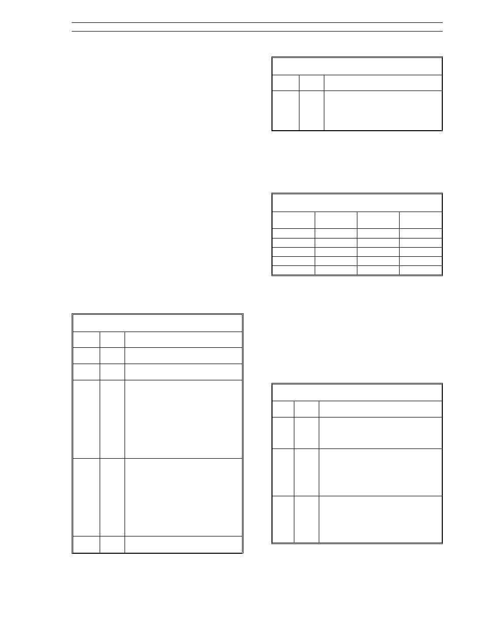
C.4.1 Database Starting Addresses
Table C-4 provides the starting address and the
number of datapoints for each data type in the
53SL6000 controller.
Table C-4. Database Starting Addresses
Type
Start
Address
Number of
Elements
Size of
Element
B
0800
H
75
1
L
084B
H
128
1/8
C
085B
H
124
3
H
09CF
H
5
5
A-F
09E8
H
2-4
10-5
C.4.2 Controller Memory Address
Scheme
The location of the datapoint in the controller mem-
ory can be calculated from the base address for
that datapoint type. The datapoint types, with their
base addresses and memory location algorithms,
are provided in Table C-5 (subscripts
H
and
D
are
used to denote hexadecimal and decimal numbers
respectively).
Table C-5. Datapoint Addresses
Type
Base
Addr
Address
Calculation
B
0800
H
Address = B Base + (B Number)
= 800
H
+ (B Number)
Address example: B012 location
= 0800
H
+ 12
D
= 800
H
+ C
H
= 80C
H
L
084B
H
Address = L Base + (L Number/8)
= 84B
H
+ (L Number/8)
Remainder = bit position in byte
Address example: L014 location
= 84B
H
+ 14/8 = 84C
H
, bit 6
(remainder).
C
085B
H
Address = C Base + (3 X C Number)
= 85B
H
+ (3 X C Number)
Address example: C011 location
85B
H
+ (3 X 11) = 85B
H
+ 33
D
= 85B
H
+ 21
H
= 87C
H
.
Appendix C. Datalink Protocol
53SL6000 Instruction Manual
C-3