7 rs-232 & rs-485 options – Micromod Micro-DCI: 53SL6000 Single Loop Controller User Manual
Page 50
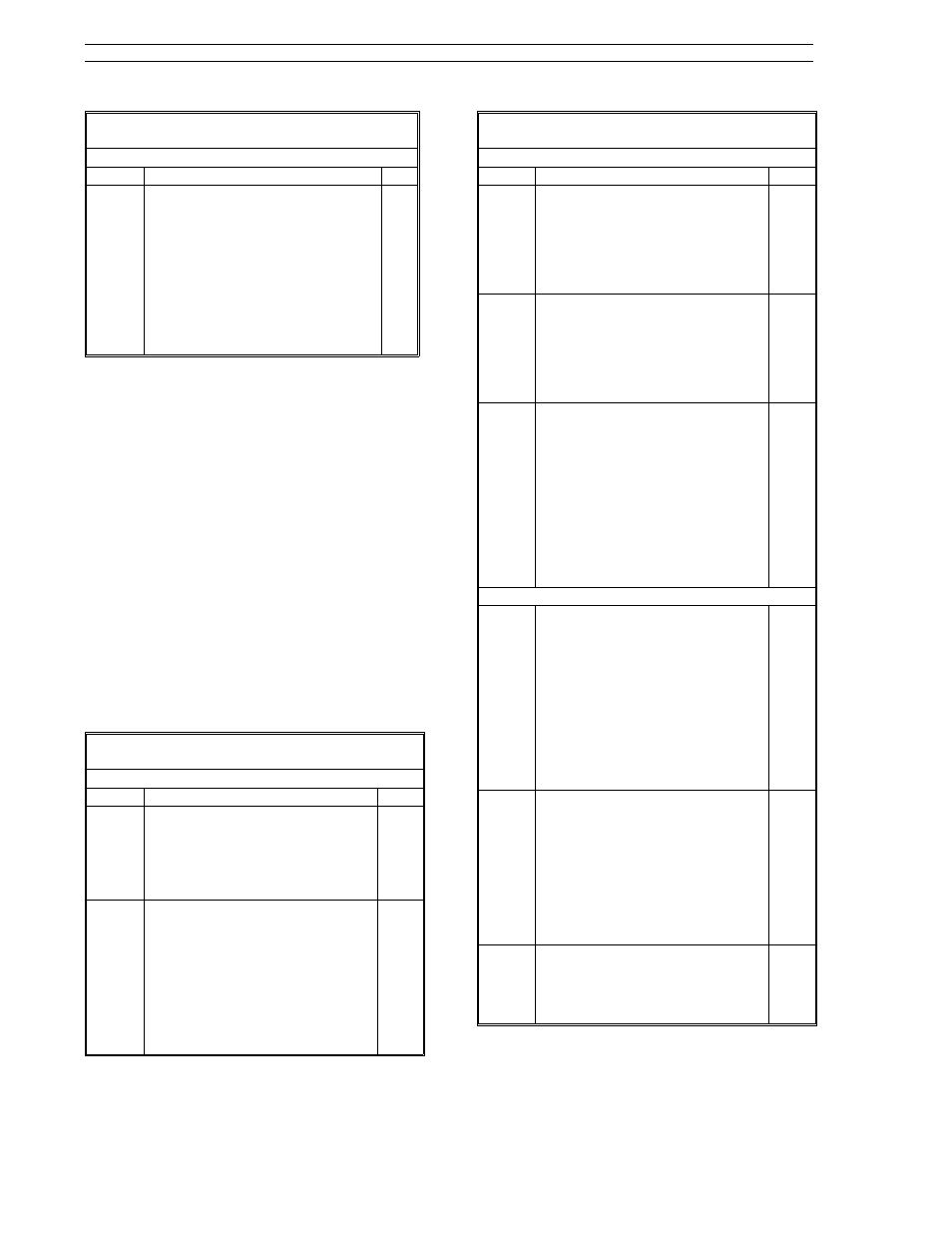
Table 5-12. Discrete Output Selections
(ProG Menu
→ do Module)
Prompt
Description
Dft
inV1 -
inV8
Discrete Output Invert
0-on: it indicates a value of zero in
the corresponding do(1-8)
registers and generates an
inactive output (typically an
open contact).
1-on: it indicates a value of one in
the corresponding do(1-8)
registers and generates an
active output (typically a
closed contact).
1-on
5.7 RS-232 and RS-485 Options
Both, the RS-232 and RS-485 communications op-
tions provide network connectivity between a host
device, typically a personal computer, and the con-
troller via the Micro-DCI Datalink protocol.
Before communications can be established be-
tween the host and the controller, both devices
must be set for the same data rate and protocol
options. Controller communications parameters
for network connectivity are provided in the conF-
SYS module described in Table 5-13. The
Micro-DCI Datalink protocol is covered in Appen-
dix C.
The RS-232 or RS-485 communications module
plugs into the rear of the controller as shown in
Figure 2-12. It is secured to the backplane with a
single mounting screw.
Table 5-13. System (SYS) Prompts
(conF Menu
→ SYS Module)
Prompt
Description (see Datalink prompts)
Dft
iA
Instrument Addrsss (Datalink)
It is the address assigned to this
controller on the datalink. Valid
addresses are from 0 - 31. No two
controllers can have the same
address on the datalink.
0
bAud
Baud Rate (Datalink)
This value is set to match the data
transfer rate of the datalink. Valid
menu selections are:
110
4800
300
9600
600
19.2K
1200
14.4K
2400
28.8K
9600
Table 5-13. System (SYS) Prompts
(conF Menu
→ SYS Module)
Prompt
Description (see Datalink prompts)
Dft
dLE
Datalink Enable (Datalink)
Selections are as follows:
on: Allows controller datalink
communication.
oFF: The controller is not permitted
to communicate over the
datalink.
on
dLP
Datalink Parity (Datalink)
Selections are as follows:
on: It indicates parity generation
and checking for even parity
serial byte protocol is enabled.
oFF: It indicates no parity protocol.
on
dLS
Datalink Stuffing (Datalink)
Selections are as follows:
on: Selects F&P byte stuffing, which
inserts a NULL (00) byte after
every SOH (7E hex) that is not
the beginning of a message.
This permits user written
communications software to
determine the number of bytes
to expect in a response
message.
oFF: Disables datalink stuffing.
on
Not Communications Parameters
tAG
Tag Name
Allows a 10 character tag to be
assigned to the controller. Four
characters maximum can be
displayed at any one time. Using
the engineer mode shift right push
button, the ten character positions
are displayed as follows:
0123
3456
6789
Characters are selected for each
position with the scroll
forward/backward push buttons.
b-FP
oPtA
Contains an identification code
provided by the module resident in
slot A at the rear of the controller
case. Codes are as follows:
0: None.
192: 2DI/2DO module.
193: Single universal analog input
module.
194: Dual universal analog input
module.
0
oPtb
Contains an identification code
provided by the module resident in
slot B at the rear of the controller
case. Codes are the same as for
oPtA above.
0
53SL6000 Instruction Manual
Section 5. Inputs/Outputs (I/O)
5-6