4 analog output 1 (ao1) – Micromod Micro-DCI: 53SL6000 Single Loop Controller User Manual
Page 48
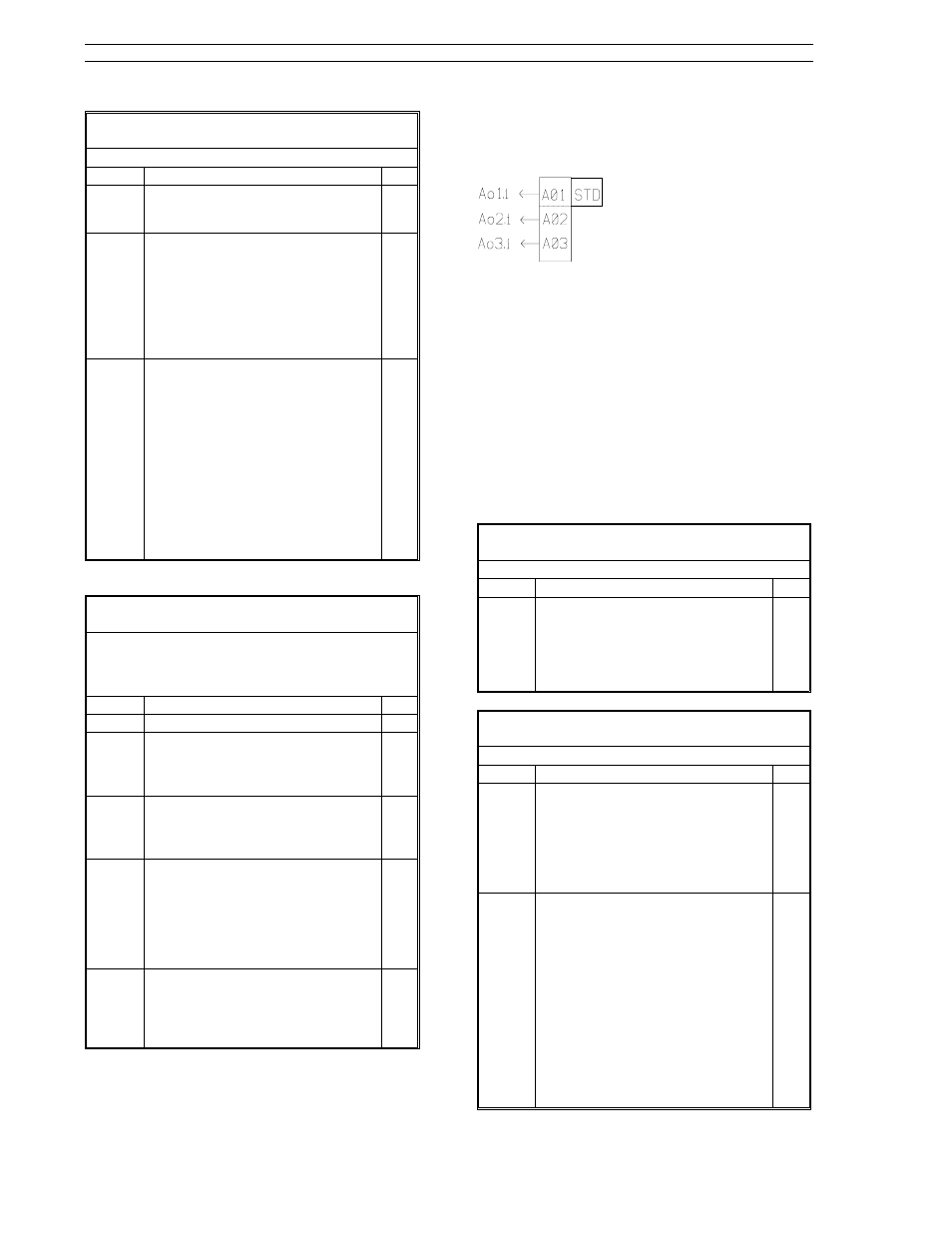
Table 5-7. Frequency/Pulse Input Types
(conF Menu
→ Ai.3, Ai.4 Modules)
Prompt
Description
Dft
tYPE
Make prompt selection from Table
5-3. Applicable types are:
FrQ1, FrQ2, FrQ3, dtot.
1-5V
SPAn
ZEro
Engineering Span, Engineering Zero
These values set the engineering
unit representation of the input
signal over the input range.
Ai
= SPAn (
input
)
+
ZEro
100.0
0.0
dFLt
Digital Filter
Specifies the time constant in
seconds for a first order filter
through which the input is
processed. The filter dampens the
higher frequency signal
components usually associated with
noise. Selections:
nonE
4.2
75.0
1200
0.3
9.0
150.0
2400
0.6
18.6
300.0
1.8
37.2
600
nonE
Table 5-8. Calibration Constants
(conF Menu
→ Ai.3, Ai.4 Modules)
If any of these values are accidentally overwritten,
reference the factory calibration sheet provided
with the controller and enter the values again.
Prompt
Description
Dft
tYPE
The prompt selection is cAL.
1-5V
biAS
GAin
Voltage Calibration Constants
These two parameters are the zero
offset and span constant for the volt
input range.
b.MV
G.MV
Millivot Calibration Constants
These two parameters are the zero
offset and span constant for the
miilivolt input range.
b.cJc
Cold Junction Compensation
Constant
This parameter accounts for the
differences between the actual
module pin temperature and the
temperature measured by the CJC
sensor from within the module.
G.rtd
RTD Hardware Compensator
This parameter accounts for the
differences in the module’s
hardware characteristics between
the 3 and 4 wire RTDs.
5.4 Analog Output 1 (AO1)
A standard 0-20 mA or 4-20
mA analog signal is trans-
m i t t e d b y t h e c o n t r o l l e r
t h r o u g h a n a l o g o u t p u t 1
(AO1). It is defined as percent
output value from 0 to 100.
The single signal conditioning parameter (bASE)
for analog output AO1 is defined in Table 5-9. Ta-
ble 5-10 lists the analog output registers and regis-
ter input connection paths; the register stores the
analog value before it is conditioned (bASE) by
hardware and transmitted. Although there are
three analog output database locations (AO1 -
AO3); only the output from AO1 is transmitted ex-
ternally by the controller. The value contents
stored in analog output registers AO2 and AO3 can
be looped-back if selected by the input connections
of the math function block or control scheme block
(only Ao3 for the control scheme block).
Table 5-9. Analog Output Selections
(conF Menu
→ Ao.1 Module)
Prompt
Description
Dft
bASE
Base Current
Specifies the signal range
corresponding to a 0 - 100% input.
Selections:
4-20 mA - 4 mA = 0%, 20 mA = 100%
0-20 mA - 0 mA = 0%, 20 mA = 100%.
4-20
Table 5-10. Analog Output Registers
(ProG Menu
→ Ao Module)
Prompt
Description
Dft
Ao1 -
Ao3
Analog Output Registers 1 - 3
Ao1 is associated with standard
output hardware Ao.1. Ao2 and
Ao3 provide loop-back to the math
function block; Ao2 also provides
loop-back to the control scheme
block.
0.0
Ao1.i
Ao2.i
Ao3.i
Analog Output Connections
Specifies the input connections for
the standard analog output Ao1
and analog outputs Ao2 and Ao3.
Input selections are as follows:
nc: No connection.
out: Control scheme out value.
Ai1: Analog input 1.
Ai2: Analog input 2.
Ai3: Analog input 3.
Ai4: Analog input 4.
Ai5: Analog Input 5.
Ai6: Analog input 6.
Ai7: Analog input 7.
out
nc
nc
53SL6000 Instruction Manual
Section 5. Inputs/Outputs (I/O)
5-4