3 universal analog input module, 1 universal analog input module parameter entries – Micromod Micro-DCI: 53SL6000 Single Loop Controller User Manual
Page 46
5.3 Universal Analog Input Module
The universal analog input module can process
one or two inputs, as determined by the type of
option installed. A single channel input module
processes one analog input (Ai3) and has one con-
nector. A dual channel input module processes
two analog inputs (Ai3 and Ai4) and has two con-
nectors. A module can not be field upgraded from
single to dual input.
NOTE: For proper thermocouple operation in a
dual channel universal input module, both
removable connector plugs must be installed in
the module.
This option can process high-level, low-level, ther-
mocouple, resistive thermal device (RTD), fre-
quency, and pulse input types. The dual channel
version can also accept any mix of these input
types at both input connectors. Each input is proc-
essed independently, as 160 db isolation is pro-
vided . Input signal characterization and shaping
are also performed, such as data linearization, cold
junction compensation (CJC), first order digital fil-
tering, and engineering unit conversion.
The module plugs into the rear of the controller at
the 10 pin option slot A connector. It is secured to
the controller case with two screws. (See Figure
2-7.)
An installed universal analog input module loads its
status identification code in the conF-SYS-oPtA pa-
rameter, as described in Table 5-13 at the end of
this book section.
5.3.1 Universal Analog Input Module
Parameter Entries
Parameter entries for the module are listed in Ta-
bles 5-3 through 5-8. Configuring the module for
any of the input types (e.g., Type J thermocouple)
requires accessing information from only two of the
tables. Table 5-3 is referenced first to correlate the
prompt assigned to the input type, followed by one
of the remaining five tables for the specific parame-
ters associated with that input type. The prompts
that do appear when a universal analog input mod-
ule is selected in the conF menu of engineer mode
represent the last type input that was specified.
Selecting the type from Table 5-3 automatically
causes the appropriate parameter suite to replace
the previous one when the scroll forward/backward
push buttons are pressed. (See Section 3 for dis-
play panel procedures.)
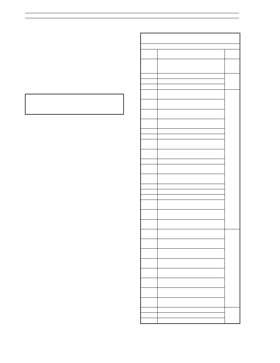
Table 5-3. Input Type Prompts
(conF Menu
→ Ai.3, Ai.4 Modules)
Prompt
Description
See
Table
oFF
oFF
This selection causes Ani value
updating to stop.
5-8
1-5V
1 to
± 5 V
5-4
0-5V
0 to 5 V
0-80
0
± 80 mV
J.tc
TC_J (-200 to +1200°C, -325 to
+2190°F)
5-5
K.tc
TC_K (-200 to +1370°C, -320 to
+2490°F)
t.tc
TC_T (-270 to +400°C, -450 to
+750°F)
E.tc
TC_E (-270 to +1000°C, -450 to
+1830°F)
r.tc
TC_R (0 to +1765°C, 32 to +3200°F)
S.tc
TC_S (0 to +1765°C, 32 to +3200°F)
b.tc
TC_B (100 to +1820°C, 215 to
+3300°F)
n.tc
TC_N (-200 to +1300°C, -320 to
+2370°F)
c.tc
TC_C (0 to +2320°C, 32 to +4200°F)
L.tc
TC_L (-200 to +900°C, -320 to
+1650°F)
u.tc
TC_U (-200 to +600°C, -325 to
+1110°F)
F.tc
TC_F (0 to +1400°C, 32 to +2550°F)
G.tc
TC_G (0 to +2320°C, 32 to +4200°F)
d.tc
TC_D (0 to +2320°C, 32 to +4200°F)
/E.tc
TC_CHE (-50 to +800°C, -50 to
+1470°F)
/S.tc
TC_CHS (0 to +1600°C, 32 to
+2900°F)
PL.tc
TC_PLII (-100 to +1395°C, -140 to
+2540°F)
Pt.85
RTD385, 100 ohm platinum (-200 to
+850°C, -320 to +1560°F)
5-6
Pt.91
RTD3911, 100 ohm platinum (-200
to +850°C, -320 to +1560°F)
Pt.92
RTD3926, 100 ohm platinum (-200
to +870°C, -320 to +1590°F)
10.c
RTD4274, 10 ohm coppper (-200 to
+200°C, -320 to +500°F)
53.c
RTD427, 53 ohm copper (-50 to
+150°C, -55 to +300°F)
100.c
RTD427, 100 ohm copper (-100 to
+260°C, -150 to +500°F)
100.n
RTD618, 100 ohm nickel (-60 to
+180°C, -80 to +350°F)
120.n
RTD672, 120 ohm nickel (-80 to
+273°C, -110 to +520°F)
FrQ1
Frequency Input 8-100 kHz
5-7
FrQ2
Frequency Input 2.5-100 kHz
FrQ3
Frequency Input 0.5-30 kHz
53SL6000 Instruction Manual
Section 5. Inputs/Outputs (I/O)
5-2