3seg mode, 2 lseg mode – Micromod Micro-DCI: 53SL6000 Single Loop Controller User Manual
Page 52
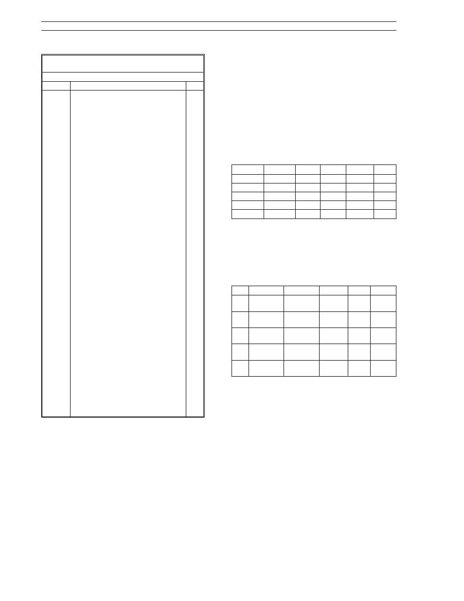
Table 6-1. Characterizer Parameters
(ProG Menu
→ chr Module)
Prompt
Description
Dft
K01 -
K26
Assignments for K01 through K26 for
the three segment (3SEG)
characterizer, linear segment (LSEG)
characterizer, the setpoint
programmer (PGrM), and the digital-
to-analog converter (DtoA) are as
follows
3SEG (executes 5 third order
polynomials):
K01 - K06: Six endpoints that
partition the 5
segments.
K07 - K10: Segment 1 (equation 1)
coefficients.
K11 - K14: Segment 2 (equation 2)
coefficients.
K15 - K18: Segment 3 (equation 3)
coefficients.
K19 - K22: Segment 4 (equation 4)
coefficients.
K23 - K26: Segment 5 (equation 5)
coefficients.
LSEG (13 ordered pairs for 12
segments. Each input value must
be greater than the previous one):
K01 - K13: input coordinates.
K14 - K26: output coordinates.
Ordered segment pairs are K01, K14;
K02, K15; etc.
PGrM:
K01 - K13: Entered time intervals in
whole seconds. Negative
numbers not permitted.
K14 - K26: Target analog output from
characterizer (per step).
DtoA:
K1: B input ramp rate (up).
K2: C input ramp rate (down).
K3: Lower output limit.
K4: Upper output limit.
0.0
6.2.1. 3SEG Mode
The third order polynomial segment characterizer
allows the user to define five adjacent segments.
Each segment has an independent third order poly-
nomial defining the relationship between the A in-
put value and the analog output value. Whenever
the A input value does not fall within any of the five
segments, a logical 1 value is produced at the char-
acterizer’s digital output; otherwise, a logical 0
value is present at the digital output. The charac-
terizer analog output value is forced to reflect the
value related to the nearest defined segment when-
ever the A input is outside all defined segments.
The five segments are defined by the constants K1
through K6. The values assigned to these con-
stants must be monotonically increasing, going
from K1 to K6, to ensure the segments are adja-
cent. Constants K7 through K26 are divided into
five groups, each with four constants. The group
acts as a set of coefficients for an individual seg-
ment’s polynomial as given by the equation and
table below:
Output
=
WA
3
+
XA
2
+
YA
+
Z
Equation Segment
W
X
Y
Z
1
K1-K2
K7
K8
K9
K10
2
K2-K3
K11
K12
K13
K14
3
K3-K4
K15
K16
K17
K18
4
K4-K5
K19
K20
K21
K22
5
K5-K6
K23
K24
K25
K26
This characterizer mode provides the capability to
linearize complex curves (e.g., thermocouple
curves). A linearization example of an E-type ther-
mocouple (operating range -115
°
to 1000
°
C) with
the characterizer A input provided in millivolts is as
follows:
Eq.
Segment
W
X
Y
Z
1
K1: -5.90
K2: 0.0
K7:
0.03947
K8:
0.1575
K9:
17.20
K10:
0.04199
2
K2: 0.0
K3: 13.42
K11:
0.004269
K12:
0.2143
K13:
17.01
K14:
0.02144
3
K3: 7.0
K4: 36.99
K15:
0.0007227
K16:
0.0769
K17:
15.12
K18:
9.264
4
K4: 36.99
K5: 61.02
K19:
0.0002274
K20:
0.02488
K21:
13.26
K22:
32.13
5
K5: 61.02
K6: 76.40
K23:
0.0001247
K24:
0.004976
K25:
11.95
K26:
60.8
Note: many of the values shown in this example
can not be entered directly at the front display
panel due to the limited size of the data entry dis-
play; however, the values given are easily loadable
via the communications network datalink interface
(requires the RS-485 option module).
6.2.2 LSEG Mode
The linear segment characterizer allows the user to
define a relationship between the A input and the
analog output value via a piecewise linear approxi-
mation. The approximation is made up of twelve
adjacent line segments. Each line segment end-
points are defined by two pairs of coordinates, re-
quir ing thirteen coor dinate pairs in all. The
coordinate values are stored in characterizer con-
stants K1-K26.
Micro-DCI
53SL6000 Controller
6-2