7 control loop parameters – Micromod Micro-DCI: 53SL6000 Single Loop Controller User Manual
Page 83
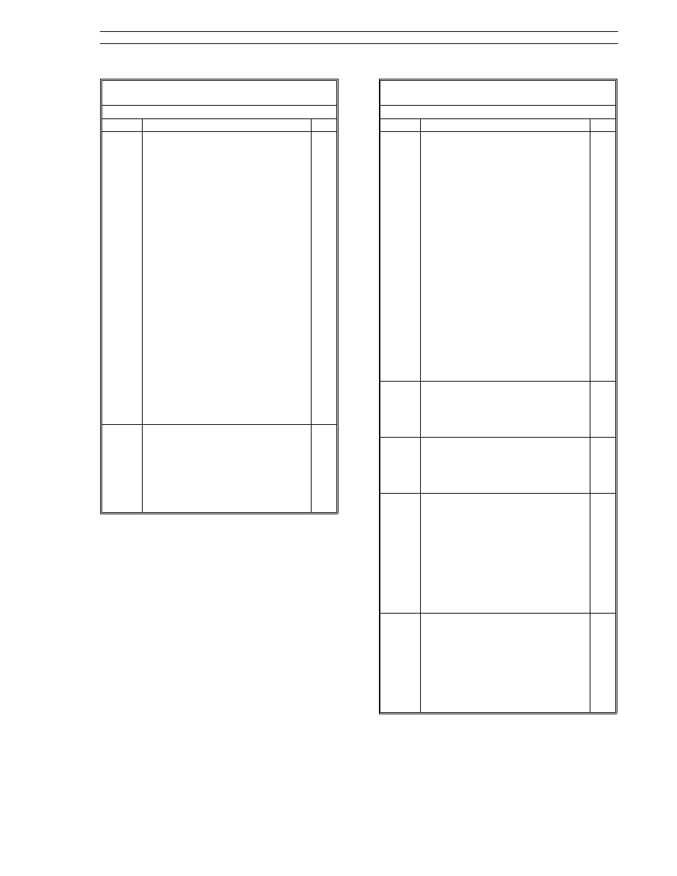
Table 7-2. Control Scheme Parameters
(ProG Menu
→ cS Module)
Prompt
Description
Dft
cS.h
cS.J
cS.K
cS.L
Control scheme cS.h - cS.L Digital
Inputs
Specifies path connections to the
cS.h - cS.L control scheme digital
inputs. Selections are as follows:
(1):
Logical one input.
(0):
Logical zero input.
di1:
Discrete input 1 logic value.
/di1:
Inverted di1 logic value.
di2:
Discrete input 2 logic value.
/di2:
Inverted di2 logic value.
di3:
Discrete input 3 logic value.
/di3:
Inverted di3 logic value.
di4:
Discrete input 4 logic value.
/di4:
Inverted di4 logic value.
di5:
Discrete input 5 logic value.
/di5:
Inverted di5 logic value.
di6:
Discrete input 6 logic value.
/di6:
Inverted di6 logic value.
di7:
Discrete input 7 logic value.
/di7:
Inverted di7 logic value.
di8:
Discrete input 8 logic value.
/di8:
Inverted di8 logic value.
Fnc:
Function generator output.
chr:
Characterizer output.
LG1:
Logic 1 module output.
LG2:
Logic 2 module output.
(1)
di2
/di1
(1)
FiX
Function Index
This parameter contains a 001 when
the controller is running and a 000
when it is stoppped. Before
configuring the controller, the
database can be defaulted to the
factory settings by entering a 098
into this parameter.
000
7.7 Control Loop Parameters
Table 7-3 lists the conF-cn.1(cn.2) configuration
parameters for both control loop modules. Some
parameters are not applicable to cn.2 and are so
noted.
Table 7-3. Control Selections
(conF Menu
→ cn.1, cn.2 Modules)
Prompt
Description
Dft
AiX
Alarm Index
Selects the type of process alarm
monitoring to be performed in the
control loop. Limit trip points are set
in PL1 and PL2 and alarm conditions
are signaled by PA1 and PA2
respectively. Selections:
h/L:
high/low alarms (PA1 active
when PV > PL1;
PA2 active when PV < PL2).
oFF:
no alarming performed.
h/- :
high alarm only (PA1 active
when PV < PL1.
-/L:
low alarm only (PA2 active
when PV < PL2).
h/hh:
high/high-high alarms (PA1
active when PV > PL1;
PA2 active when PV > PL2).
L/LL:
low/low-low alarms (PA1
active when PV < PL1;
PA2 active when PV < PL2.
dEV:
PA1 active when PV-SP>PL1 h/L for cn.1, oFF cn.2 PL1 Process Limit 1 100.0 PL2 Process Limit 2 0.0 Adb Alarm Deadband 2.000 Pb Proportional Band (see Section 9.2) 100.0 Section 7. Control Scheme Block 53SL6000 Instruction Manual 7-25
PA2 active when PV-SP
for
Specifies the process or deviation
value which triggers the alarm
associated with PA1 as determined
by AiX.
Specifies the process or deviation
value which triggers the alarm
associated with PA2 as determined
by AiX.
Specifies the hystersis (gap)
between alarm trigger and reset.
This value is used to eliminate
repetitive alarm triggering when the
process is fluctuating about a
process limit. This value should be
set slightly larger then the peak-to-
peak fluctuations (noise) which are
normally present in the process
variable signal.
Specifies the percent of process
deviation from setpoint over the
control range (ir) required to
generate a full scale output signal.
For a detailed discussion on control
and tuning, see Section 9. Values
should be limited between 2 to
1000%.