0 functional overview, 1 simplified block diagram – Micromod Micro-DCI: 53SL6000 Single Loop Controller User Manual
Page 40
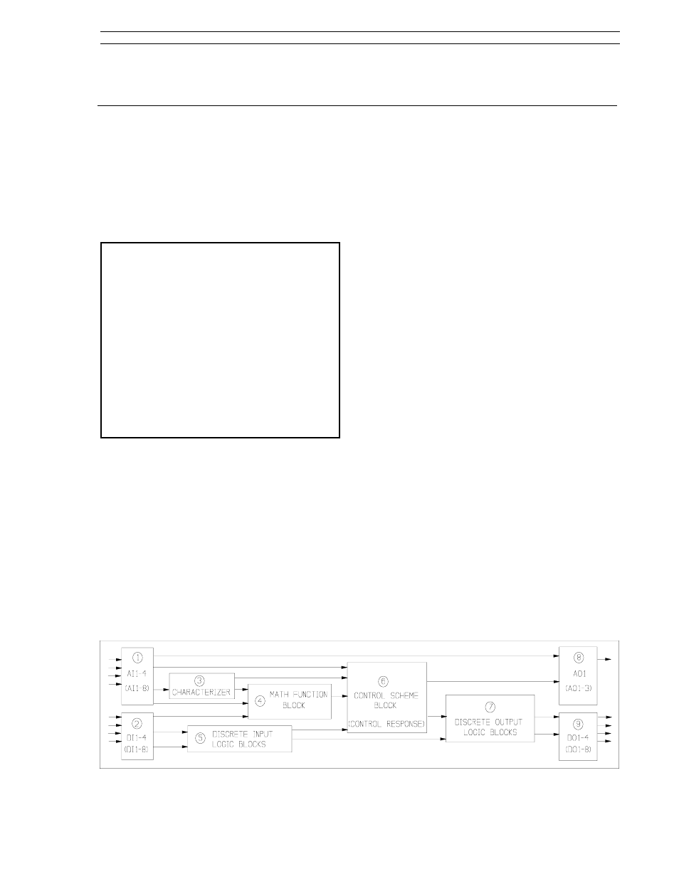
4.1 Simplified Block Diagram
As shown in Figure 4-1 below, the internal opera-
tions of the 53SL6000 Controller can be classified
into nine major functional areas. An overview of
these functional areas is provided in this section;
additional information is provided in Sections 5
through 7.
NOTE: Although external analog connections to
the controller are two standard inputs, two optional
inputs, and one output, there are in fact eight
analog input registers (AI1-8) and three analog
output (AO1-3) registers available in the controller
database. The discrete digital external
connections include two standard inputs, two
optional inputs, two standard outputs, and two
optional outputs. There are, however, eight
discrete input database registers (DI1- DO8) and
eight discrete output database registers (DO1-
DO8). Registers not assigned to standard or
optional external I/O functions can be loaded with
constant values to simulate known process events
or hold process values for access through datalink
communications or for display.
1.
Analog Inputs 1-4 (AI1-4) - accept the 0/4- 20
mA input signals. Analog inputs 3 and 4 re-
quire the universal analog input module. The
signal values are stored in the analog regis-
ters. There are eight analog input registers,
AI1-AI8. Analog input registers AI5-AI8 do not
accept external signals, but can be loaded with
constant values.
2.
Discrete Inputs 1-4 (DI1-4) - accept voltages
0-1 V or 4-24 V, which are converted to logic
levels 1 and 0 respectively. Digital inputs 3
and 4 require the 2DI/2DO module. There are
eight digital input registers, DI1-DI8. Digital
input registers DI5-DI8 do not accept external
signals, but can be loaded with logic level val-
ues 0 or 1.
3.
Characterizer - provides four operating modes,
three of which are used to modify input signal
values before being passed on to the analog
math function block or control scheme block;
the other operating mode generates a ramp
and hold output value. The four operating
modes are as follows:
•
Five third order polynomial segments
•
Twelve segment linearizer
•
Setpoint programmer (ramp and hold)
•
Digital-to-Analog converter
4.
Math Function Block - provides nine different
equations for analog input signal augmenta-
tion. The equations are as follows:
•
Algebraic
•
Summation
•
Polynomial
•
Power
•
Logarithmic
•
Limiter
•
Selector
•
Linear Gas Flow Compensation
•
Square Root Gas Flow Compensation
4.0 Functional Overview
Figure 4-1. Simplified Controller Block Diagram
Section 4. Functional Overview
53SL6000 Instruction Manual
4-1