8 engineer mode oper selections – Micromod Micro-DCI: 53SL6000 Single Loop Controller User Manual
Page 36
•
If exiting the conF or ProG menus in engineer
mode, the controller goes offline and a blinking
oFF prompt appears in the red dro immediately
after the mode pb is pressed. To put the con-
troller in operator mode, press the scroll for-
ward pb to change the oFF prompt to the run
prompt and press the enter pb.
•
The controller may have been powered-down
in offline, in which case it will return to offline
after the status and power-on self test se-
quence is complete. To put the controller in
operator mode if an offline indication occurs
after the power-up sequence, perform the fol-
lowing steps:
1.
press and hold the mode pb until a menu
item (conF, oPEr, or ProG) appears.
2.
Use the scroll forward push button to dis-
play the ProG or conF menu prompts and
press the select push button.
3.
Press the mode pb; the oFF prompt ap-
pears blinking in the red dro.
4.
To put the controller in operator mode,
press the scroll forward pb to change the
oFF prompt to the run prompt and press
the enter pb.
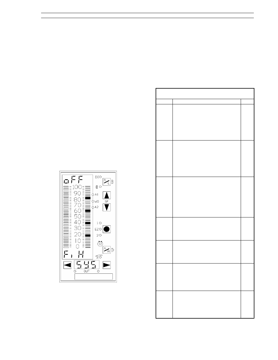
Figure 3-11. Offline Display Pattern
3.8 Engineer Mode oPEr Selections
This menu provides operator access to selected
parameters and auxiliary inputs. Items not enabled
from the oPr module of the conF menu will not
appear in the oPEr menu. The oPEr parameters
and auxiliary inputs are described in Table 3-3 and
their enabling parameters are described in Table
3-4 as follows:
Table 3-3. oPEr Menu Selections
Prompt
Description
Dft
di7
Discrete Input 7
It provides enumerated selections,
StoP and run, that can be used to
implement general purpose logic
states.
StoP - 0
run - 1
(It is enabled with conF-oPr-di7.E.)
StoP
di8
Discrete Input 8
It provides enumerated selections,
oFF and on, that can be used to
implement general purpose logic
states.
oFF - 0
on - 1
(It is enabled with conF-oPr-di8.E.)
oFF
StEP
Setpoint Programmer StEP
It indicates the step being
executed by the programmer . It
can also be used to force the
setpoint programmer to a new
step. The setpoint programmer step
sequence execution is from 0 to 12;
13 indicates the program is done.
(It is enabled with conF-oPr-StP.E.)
0
Ai7
Analog Input 7 Register
It provides operator access to
analog input register 7. (See Table
5-2.)
(It is enabled with conF-oPr-Ai.E.)
0.0
Ai8
Analog Input 8 Register
It provides operator access to
analog input register 8. (See Table
5-2.)
(It is enabled with conF-oPr-Ai.E.)
0.0
PL1
Process Limit 1
Specifies the process or deviation
value which triggers the alarm
associated with PA1 as determined
by conF-cn.1(cn.2)-AiX. (It is
enabled with conF-oPr-ALM.E.)
100.0
PL2
Process Limit 2
Specifies the process or deviation
value which triggers the alarm
associated with PA2 as determined
by conF-cn.1(cn.2)-AiX. (It is
enabled with conF-oPr-ALM.E.)
0.0
Section 3. Display Panel
53SL6000 Instruction Manual
3-9