Micromod Micro-DCI: 53SL6000 Single Loop Controller User Manual
Page 30
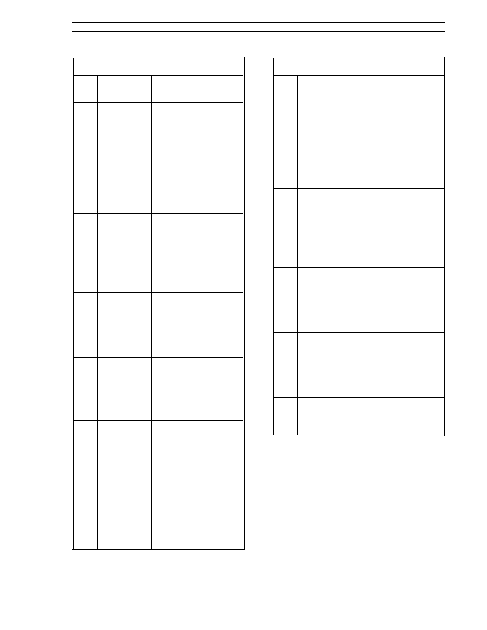
Table 3-1. Operator Mode Display Items
Item
Call-Out
Description
1
PV dro
It is the process variable
value in engineering units.
2
PV bar
It indicates the process
variable percent of control
range.
3
PV Alarm 1
Status
When active, it indicates
alarm 1 of the selected
alarm index limits (e.g.
high/low alarms; high, high-
high alarms; etc.) was not
within tolerable limits.
For high/low alarms, an
active Alarm 1 LED
indicates the the PV
exceeded the high
alarmed value.
4
PV Alarm 2
Status
When active, it indicates
alarm 2 of the selected
alarm index limits (e.g.
high/low alarms; low, low-
low alarms; etc.) was not
within tolerable limits. For
high/low alarms, an active
Alarm 2 LED indicates the
PV fell below the low
alarmed value.
5
Setpoint dro
It is the setpoint value in
engineering units or a ratio
setpoint.
6
Setpoint bar
It indicates the setpoint
percent of control range.
It also produces a striped
pattern when the
controller is offline.
7
R/L
Push
Button
Generally, it is used to
select the setpoint source:
remote or local setpoint
control. Remote setpoint
control requires an active
Remote Enable. For ratio
control, it is used to select
ratio or standard control.
8
Remote
Setpoint
Status
It indicates remote
setpoint is selected with
the R/L push button. See
item 7 above and the LED
chart in Figure 3-2.
9
Local
Setpoint
Status
It indicates the local or
tracking setpoint is
selected with the R/L push
button. See item 7 above
and the LED chart in Figure
3-2.
10
Setpoint
Up
Push
Button
Pressing this push button
increases the local
setpoint or ratio setpoint
value. See Table 3-2 for
setpoint mode selections.
Table 3-1. Operator Mode Display Items
Item
Call-Out
Description
11
Setpoint
Down pb
Pressing this push button
decreases the local
setpoint or ratio setpoint
value. See Table 3-2 for
setpoint mode selections.
12
Out dro
It is the control output as a
percent of control range.
It can also be used to
display an externally
generated signal such as a
proportional speed
floating control valve
position indication.
13
A/M
Push
Button
It is used to select auto or
manual control. If auto is
selected and Auto Enable
is active, then the output is
determined by the
controller PID algorithm. If
manual is selected, the
output is determined by
the decrease/increase out
push buttons.
14
Auto
Status
It indicates auto operation
is selected with the A/M
push button. See the LED
chart in Figure 3-2.
15
Manual
Status
It indicates manual
operation is selected with
the A/M push button. See
the LED chart in Figure 3-2.
16
Decrease Out
Push
Button
When in manual
operation, pressing this
push button causes the
output to decrease.
17
Increase Out
Push
Button
When in manual
operation, pressing this
push button causes the
output to increase.
18
Multistate 1
Indicators
These two indicators
activate to show the
direction of the discrete
control output.
19
Multistate 2
Indicators
Section 3. Display Panel
53SL6000 Instruction Manual
3-3