8 proportional speed floating control – Micromod Micro-DCI: 53SL6000 Single Loop Controller User Manual
Page 101
8.8 Proportional Speed Floating
Control
This control output is suitable for any of the control
schemes where the final control element is usually
a motorized valve. The controller output is pro-
vided at two discrete outputs, rather than the ana-
log output AO1. One discrete output drives the
motor in one direction and the other discrete output
drives the motor in the opposite direction. The MS1
and MS2 indicators activate, depending on the DO
driving the motor. The discrete output logic asserts
for a period of time that is proportional to the quan-
titative requirement of the corrective action. The
greater the error, the longer the discrete output
logic will be asserted. If the deviation is zero and
there is no signal on either discrete output, the
motor can be at any position within its operating
range; therefore, the motorized valve is said to be
floating. Since the motorized valved is moved at a
speed proportional to the deviation, and floats
when there is no output signal, this output type is
called proportional speed floating control.
8.8.1 Motorized Valve Connections
The 2DI/2DO option module is required for propor-
tional speed floating control because the standard
discrete outputs DO1 and DO2 do not have relays.
It is NOT recommended that DO1 and DO2 be
used for this output application, as doing so
would require a motor interface (e.g., relays or
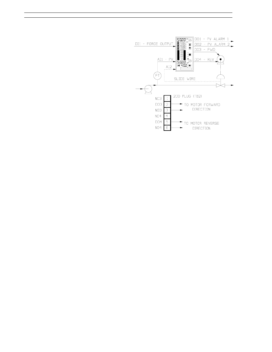
triac circuitry). An illustration of proportional
speed floating control output is provided in Figure
8-16. Also shown in the illustration are the wiring
connections at the 2DI/2DO module connector
TB2. The motor connections are not shown due to
product variations. The user must ascertain how
the leads are connected at the motor to cause it to
drive in the required direction for each active out-
put.
8.8.2 Configuration Requirements
Parameter inputs and path connections are re-
quired to initiate proportional speed floating con-
trol. The parameters affected apply only to control
module 1 (cn.1) of the conF menu and not control
module 2 (cn.2). The applicable path connections
and parameter entries are as follows:
Figure 8-16. Proportional Speed Floating
Control
Switch path connections (these switches can
be found in the cS module of the ProG menu):
•
ProG-do-do3.i should be at its default connec-
tion to Vup.
•
ProG-do-do4.i should be at its default connec-
tion to Vdn.
•
ProG-cS-doFb should be set to on if a valve
slide wire is to be used.
•
ProG-cS-cs.F should be connected to Ai.2.
This allows the slide wire feedback (see Figure
8-16) at Ai2 to be displayed in the yellow dro.
The value displayed is in percent of the valve
position and not percent output. This is an
optional connection because some valves do
not provide slide wire output.
Parameter entries:
•
Zero-out Manual Rest (conF-cn.1-Mr). Allow
full control range by setting output low-limit
(conF-cn.1-oL) to -100 and output high-limit
(conF-cn.1-oh) to 100.
•
Enter an output duty cycle value in seconds in
conF-cn.1-dcp. This value specifies, in sec-
onds, the length of the cycle period over which
the digital outputs VuP and Vdn are calculated.
This time must be set based on the charac-
teristics of the final control element and the
amount of cycling permitted. A shorter dcp
increases motor cycling and a longer dcp de-
creases motor cycling, which slows the control
response. For minimum cycling of the final
53SL6000 Instruction Manual
Section 8. Eight Control Strategies
8-14