0 display panel, 1 display panel overview, 2 operational mode – Micromod Micro-DCI: 53SL6000 Single Loop Controller User Manual
Page 28
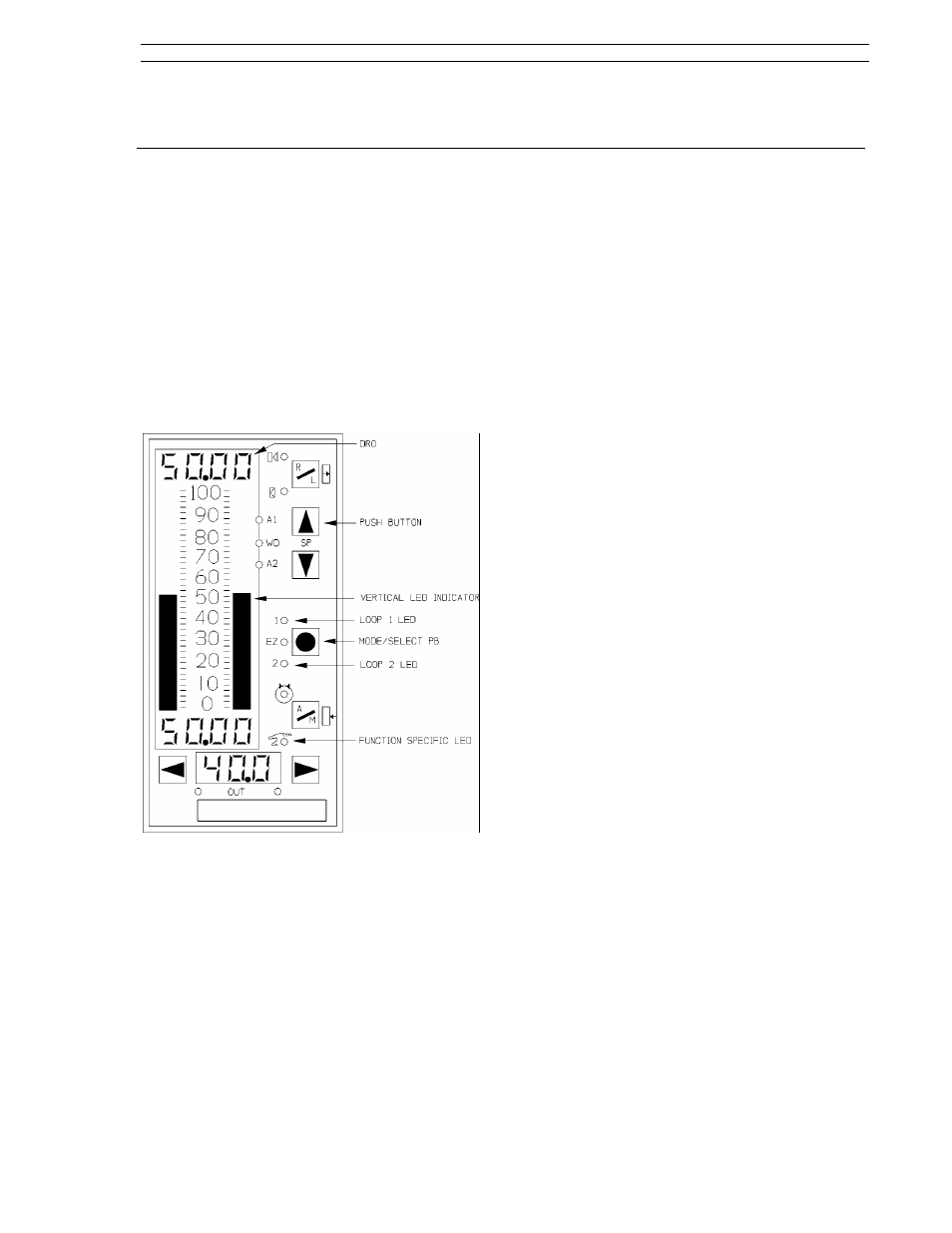
3.1 Display Panel Overview
As shown in Figure 3-1, the controller display panel
contains three digital read-out (dro) fields, two ver-
tical bar indicators, twelve function specific status
indicators, and seven push buttons (pbs). The dis-
play panel is used to alter controller settings (which
in turn affect process operation), to monitor proc-
ess operation, and to configure controller function-
ality. (It is also used to commission the controller,
which is described in Section 9.) Process opera-
tion is altered and monitored with the controller in
operator mode; controller functionality is config-
ured with the controller in engineer mode.
Figure 3-1. Display Panel Overview
3.2 Operator Mode
The colors red, green, and yellow are used to visu-
ally partition the display panel into general operat-
ing mode functional areas as follows:
•
red - process variable presentation.
•
green - setpoint presentation and control.
•
yellow - output presentation and control.
Red: The red display area includes the left vertical
bar, upper dro, and alarm status indicators (A1,
A2). This display area is assigned to the process
variable input. The red vertical bar indicates the
process variable as a percent of control range and
the red dro is the process variable in engineering
units.
Green: The green display area includes the right
vertical bar, the dro immediately beneath it, the
remote/local pb with its two status indicators, and
the setpoint up/down pbs. This display area is usu-
ally assigned to setpoint indication and control, al-
though the green vertical bar and dro can be used
to indicate a second process variable if the se-
lected control scheme is an indicator. The green
vertical bar indicates the setpoint as a percent of
control range and the green dro is the value in
engineering units.
Yellow: The yellow display area includes the bot-
tom dro, the auto/manual pb with its status indica-
tors, the output pbs, and the two multistate (MS1,
MS2) indicators. This display area is primarily as-
signed to output indication and control. The yellow
dro is an output value in percent of the scaled final
control element travel range.
3.2.1 Operator Mode Panel Functions
The operator mode panel functions are described
in Figure 3-2 on the next page. The figure has
three major parts: an illustration of the controller
with item number call-outs in the upper right, a
supporting chart in the upper left that defines the
Off/On/Blinking status indicator states, and a sum-
mary chart at the bottom that lists the assigned
functions of each item call-out by control scheme.
The illustration item call-outs are defined in more
detail in Table 3-1.
As shown in Figure 3-2, many of the push buttons
and status indicators have identical functions in the
different control schemes; however, the indica-
tor/loader (in.Ld) control scheme is the most
unique.
3.0 Display Panel
Section 3. Display Panel
53SL6000 Instruction Manual
3-1