0 inputs / outputs ( i/o ), 1 i/o overview, 2 analog inputs – Micromod Micro-DCI: 53SL6000 Single Loop Controller User Manual
Page 45: 0 inputs/outputs (i/o)
5.1 I/O Overview
This section provides functional descriptions and
applicable parameter definitions for all of the con-
troller inputs and outputs to include the following:
•
Analog Inputs
•
Universal Analog Input Module
•
Analog Output
•
Discrete Inputs
•
Discrete Outputs (and 2DI/2DO Module)
•
RS-232 and RS-485 Modules
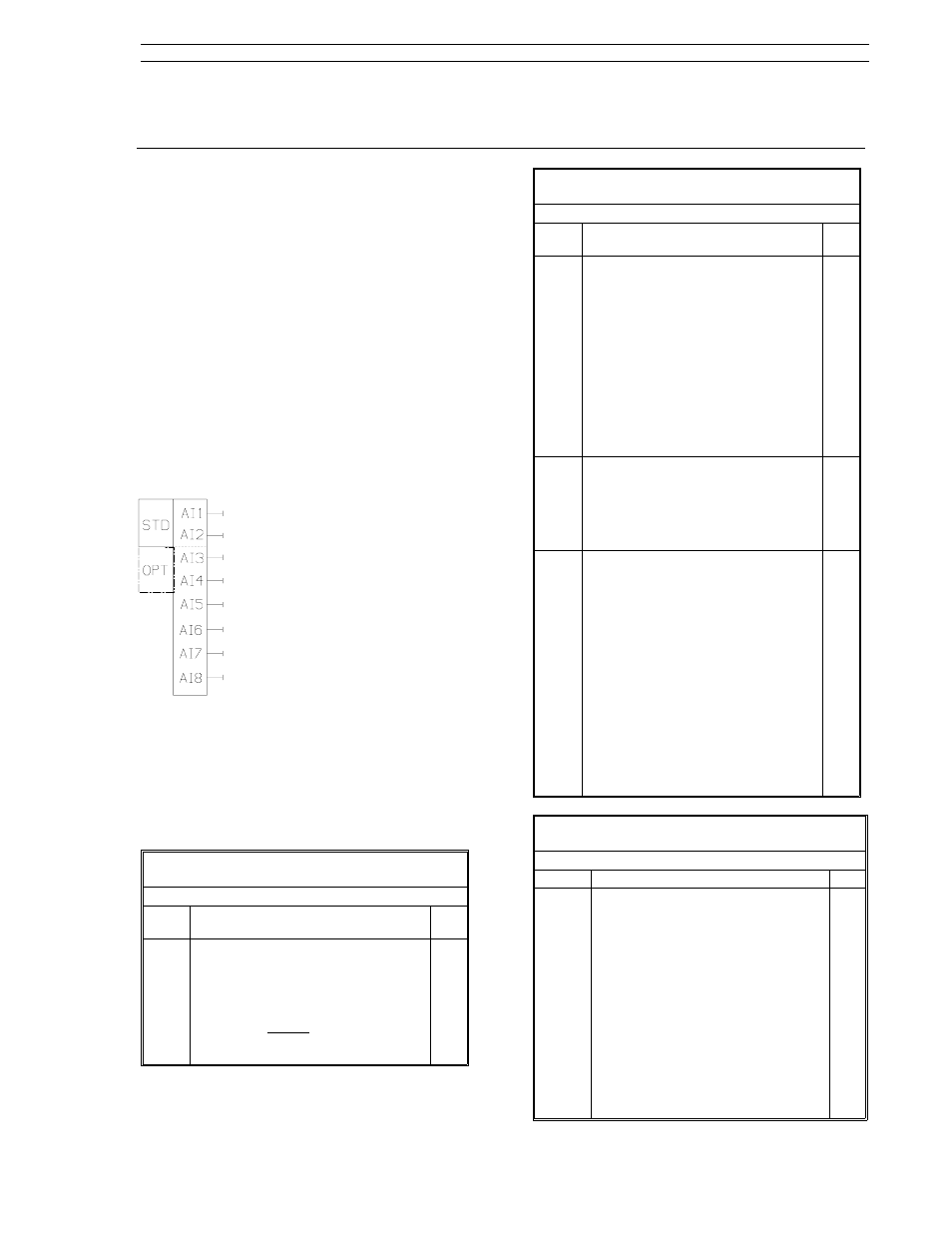
5.2 Analog Inputs
Standard 0-20 mA or 4-20 mA analog
input signals are received by the con-
troller through analog input modules
1 and 2 (Ai.1, Ai.2). The input current
range is selectable as are other pa-
rameters that can be used to apply
conditioning to the signal. The meas-
ured input value is in engineering
units and is stored in the analog reg-
ister after all signal conditioning de-
f i n e d b y t h e a n a l o g m o d u l e
parameters is applied.
The signal conditioning parameters for analog input
modules Ai.1 and Ai.2 are defined in Table 5-1.
The parameter set is identical for each of the two
analog input modules. Table 5-2 lists the analog
input registers; the register actually stores the ana-
log value.
Table 5-1. Analog Input Selections
(conF Menu
→ Ai.1, Ai.2 Modules)
Prompt
Description
Dft
SPAn
ZEro
Engineering Span, Engineering Zero
These values set the engineering unit
representation of the input signal
over the input range.
Ai
= SPAn
input%
100
+ ZEro
100.0
0.0
Table 5-1. Analog Input Selections
(conF Menu
→ Ai.1, Ai.2 Modules)
Prompt
Description
Dft
SQrt
Square Root Signal
Speciifies whether the analog input
signal requires square root
characterization (as would be the
case for a differential pressure
transducer across an orifice plate),
or linear interpretation. Selections:
Lin: Linear interpretation.
SQrt: Square root characterization.
(For SQrt selection, the value
of Ai is forced to 0.0 at low in-
put signal levels [<6.25%] to pre-
vent large signal oscillations.)
Lin
bASE Base Current
Specifies the signal range
corresponding to a 0 - 100% input.
Selections:
4-20 mA - 4 mA = 0%, 20 mA = 100%
0-20 mA - 0 mA = 0%, 20 mA = 100%.
4-20
dFLt
Digital Filter
Specifies the time constant in
seconds for a first order filter through
which the input is processed. The
filter dampens the higher frequency
signal components usually
associated with signal noise. The
larger the selected value, the lower
the frequency affected and the
greater the dampening to the
higher frequencies. Selections:
nonE
0.7
12.7
205
0.05
1.5
25.5
410
0.1
3.1
51.1
819
0.3
6.3
102
1638
0.3
Table 5-2. Analog Input Registers
(ProG Menu
→ Ai Module)
Prompt
Description
Dft
Ai1 -
Ai8
Analog Input Registers 1 - 8
Registers Ai1and Ai2 are capable of
receiving hardware inputs from
modules Ai.1 and Ai.2. All signal
shaping (e.g., ZEro, SPAn, SQrt,
bASE, dFLt etc.) is performed by the
hardware modules before the value
is entered into the register. Registers
Ai3 - Ai4 can also receive hardware
inputs from an installed universal
analog input module. Constant
values can be entered into registers
Ai1 - Ai8 if the span and zero are
both set to 0 to prevent overwriting
register contents.
0.0
5.0 Inputs/Outputs (I/O)
Section 5. Inputs/Outputs (I/O)
53SL6000 Instruction Manual
5-1