7 dual indicator with re-transmitted pv – Micromod Micro-DCI: 53SL6000 Single Loop Controller User Manual
Page 100
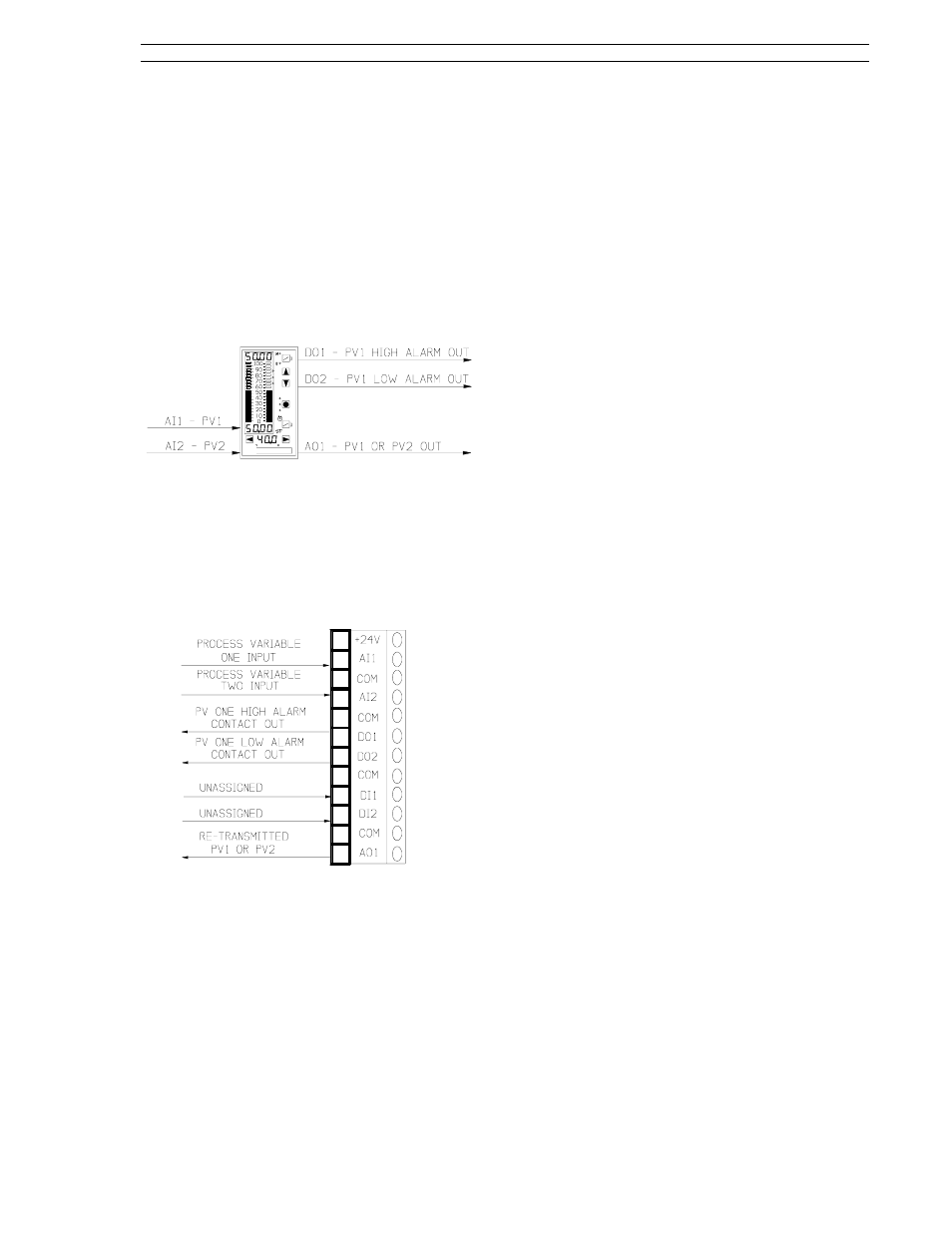
8.7 Dual Indicator with
Re-Transmitted PV
The Dual Indicator allows two process variables to
be displayed and either one to be selected as the
output at AO1. The process variables are input
into AI1 and AI2. A dual indicator application is
illustrated in Figure 8-14.
This application is implemented with the controller
default settings and the in.Ld control scheme.
Figure 8-14. Dual Indicator Application
The signal connector is illustrated in Figure 8-15
and the connector pin assignment descriptions are
provided in the sections that follow. These sec-
tions also contain the applicable display prompts
that may require configuration changes.
Figure 8-15. Dual Indicator Signals
8.7.1 AI1 - PV1 Input
Process Variable 1 is the analog signal that is
checked to be within acceptable process limits. It
can be re-transmitted as the selected controller
output.
Applicable parameters that may require configura-
tion changes:
Section 5.2, conF- Ai.1-(SPan, ZEro, SQrt, bASE,
dFLt).
For PV alarms:
Section 7.7, conF-cn.1-(AiX, PL1, PL2, Adb).
8.7.2 AI2 - PV2 Input
Process Variable 2 is a displayed analog signal
that can be re-transmitted as the selected control-
ler output.
Applicable parameters that may require configura-
tion changes:
Section 5.2, conF-Ai.2-(SPan, ZEro, SQrt, bASE,
dFLt).
8.7.3 DO1 - PV1 High Alarm Contact
Out
D01 is closed (on) when the process variable 1
value is not within the cn.1 process alarm limit 1
(PL1) setting.
Applicable parameter that may require configura-
tion change:
Section 5.6, ProG-do-inV1.
8.7.4 DO2 - PV1 Low Alarm Contact
Out
D02 is closed (on) when the process variable 1
value is not within the cn.1 process alarm limit 2
(PL2) setting.
Applicable parameter that may require configura-
tion change:
Section 5.6, ProG-do-inV2.
8.7.5 A01 - Retransmitted PV1 or PV2
This is a re-transmitted output of either the PV1 or
PV2 input, depending on the Ao1.i path connection
(to Ai1 or Ai2).
Applicable parameters that may require configura-
tion changes:
Section 5.4, ProG-Ao-Ao1.i.
Section 7.7 - conF-cn.1-(oh, oL, hML, oSr, rSW,
rSV).
8.7.6 SchM Selection
The dual indicator is implemented with the control-
ler default settings and in.Ld (indicator/loader) se-
lected from the SchM prompt of the cS module.
Applicable parameter that requires configuration
change:
Section 7.6, ProG-cS-SchM.
Section 8. Eight Control Strategies
53SL6000 Instruction Manual
8-13