6 universal analog input module – Micromod Micro-DCI: 53SL6000 Single Loop Controller User Manual
Page 24
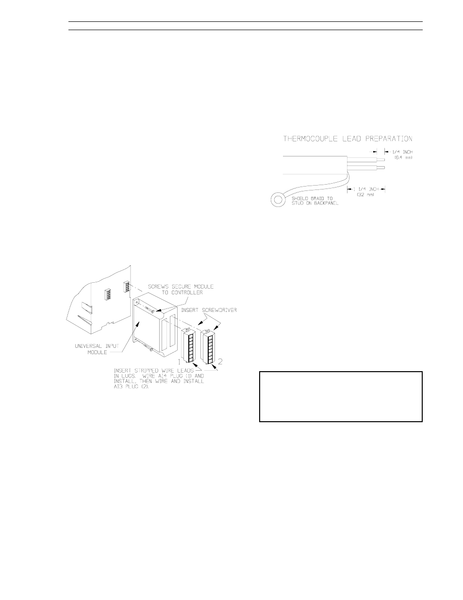
2.6 Universal Analog Input Module
This information applies to only those controllers
with an optional universal analog input module.
2.6.1 Universal Analog Input Module
Backplane Installation
Figure 2-7 illustrates the universal analog input
module location on the controller backplane. The
universal input module is socket mounted and is
secured to the backplane with two screws. Also
shown in Figure 2-7 are the signal plugs AI3 (right
plug) and AI4 (left plug) that are screw mounted to
the universal analog input module (the plug mount-
ing screws are not illustrated). Depending on the
option ordered, one (AI3) or both (AI3 and AI4) of
these plugs will require installation and input con-
nections. The plugs for AI3 and AI4 are identical;
therefore, care should be taken to ensure each
plug is installed in its proper location. Each plug,
however, is keyed to prevent inverted insertion into
its module connector.
Figure 2-7. Universal Analog Input Module
2.6.2 Universal Analog Input Module
Signal Wiring
As shown in Figure 2-7 (e.g., INSERT SCREW-
DRIVER), the signal wire lug screws are accessed
on the side of each plug.
Each analog input (AI3 and AI4) can accept only
one device input configuration as illustrated in Fig-
ure 2-8. Unused plug lugs can not be dedicated
to another input.
2.6.2.1 Thermocouple Connections and
Burn-out Detection
To ensure proper cold junction compensation
(CJC) operation, the steps to wire a thermocouple
to the universal analog input module are as follows:
1.
Prepare the thermocouple leads as shown in
the following illustration:
2.
For dual universal analog input modules that
will have one thermocouple connected, ensure
it is installed on AI3 and that the other input is
installed on AI4.
3.
For dual universal analog input modules that
will have only one terminal plug connected, the
other terminal plug must still be installed on the
module for proper performance.
4.
Thermocouple Burn-out Detection - A s
shown in Figure 2-8, an open thermocouple
detection (OTD) current, which is very small, is
provided at pin 3 of each connector plug. If pin
3 is wired to pin 1 and the thermocouple opens,
then a positive temperature over range results.
If pin 3 is wired to pin 2 and the thermocouple
opens, then a negative temperature over range
results.
NOTE: If an upscale or downscale open
thermocouple detection (OTD) wire is installed as
part of the thermocouple connection, then the wire
should be 2 inches (50.8 mm) of 22AWG wire or
lighter. Do not use longer or heavier gauge (e.g.,
14AWG) wire.
5.
The complete assembly will reach thermal
equilibrium approximately 30 minutes after the
controller is powered up (see Section 2.9, Ap-
plying Power).
Section 2. Installation and Power-Up Procedures
53SL6000 Instruction Manual
2-5