5 engineer mode – Micromod Micro-DCI: 53SL6000 Single Loop Controller User Manual
Page 32
3.5 Engineer Mode
The controller parameters and path connections
are configured in engineer mode. Engineer mode
is also used to initiate the Easy-Tune sequence
(see Section 9.8). This mode is entered when the
mode push button is held pressed for an extended
period of approximately 3 seconds, at which time
the oPEr menu prompt appears in the green dro.
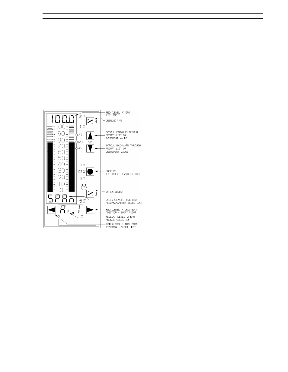
3.5.1 Engineer Mode Display Panel
The display panel functions for engineer mode are
described in Figure 3-4 as follows:
Figure 3-4. Engineer Mode Display Panel
3.5.2 Engineer Mode Hieracrhical
Structure
Engineer mode is a hierarchical structure of nested
prompt layers that can be four levels deep; the
general order of selection is:
•
Level 1, Menu - After engineer mode is ac-
cessed with the mode push button, each menu
prompt can be displayed sequentially by press-
ing the scroll forward pb. The menu prompts
are three major display panel paths: oPEr,
ProG, and conF. The ProG and conF paths
can each be protected with their own unique
pass-key. The three menu prompts are de-
scribed as follows:
1.
oPEr (operator) - provides quick access
for operators to display and configure com-
mon parameters such as alarm limits,
deadband, etc. (This path skips level 2,
module described below.)
2.
ProG (Program) - is selected to enter reg-
ister values, formula constants, and to
make path connections. Parameters en-
tered in this menu will force the controller
offline. It is used primarily by engineering
personnel.
3.
conF (Configure) - is selected to configure
online database parameters; it is used pri-
marily by engineering personnel.
•
Level 2, Module Select - used to select a spe-
cific controller functional element (e.g., the
prompt Ai.1 for analog input 1). The full path
name is indicated by menu-module (e.g., conF-
Ai.1). The module selection is skipped in the
oPEr menu path.
•
Level 3, Parameter Select - used to select a
specific parameter from a list of module pa-
rameters (e.g., the parameter prompt SPAn un-
der Ai.1). The full path name is indicated by
menu-module- parameter (e.g., conF-Ai.1-
SPAn).
•
Level 4, Edit - this is where a value is entered
for the displayed parameter or a selection from
a list of values or mnemonics is made.
3.5.2.1 Editing a Parameter
Figure 3-5 illustrates the steps to edit a parameter
in engineer mode. In the illustration a parameter
selection is made; some parameters require a nu-
meric value to be entered. The process to edit a
parameter is reiterative:
•
When engineer mode is entered, the oPEr
menu prompt (level 1) appears in the green
dro. The menu prompts are scrolled and one
is selected.
•
Selecting a menu prompt causes the first mod-
ule prompt (level 2) to appear in the yellow dro.
The module prompts of the selected menu are
scrolled and one is selected.
•
Selecting a module prompt causes the first pa-
rameter prompt (level 3) to appear; it replaces
the menu prompt in the green dro. The pa-
rameter prompts of the selected module are
scrolled and one is selected.
•
Selecting a parameter prompt causes the first
edit entry prompt (level 4) to appear in the red
dro. An edit input list is scrolled and an item is
selected or a numeric value is entered.
Section 3. Display Panel
53SL6000 Instruction Manual
3-5