B.3 removal & replacement, B.3 removal and replacement – Micromod Micro-DCI: 53SL6000 Single Loop Controller User Manual
Page 119
WARNING:
Always remove power before
attempting to install, disassemble, or service the
controller. Failure to remove power may result in
serious personal injury and/or equipment damage.
CAUTION: - Use a grounded wrist strap to prevent
damage to integrated circuit devices when handling
circuit boards.
NOTE: - When communicating with
MicroMod
for replacement parts, reference the
controller’s serial number to ensure the correct
replacement is supplied. The necessary ordering
information is provided on the instrument data tag
and on the manufacturing specification sheet
supplied with the controller.
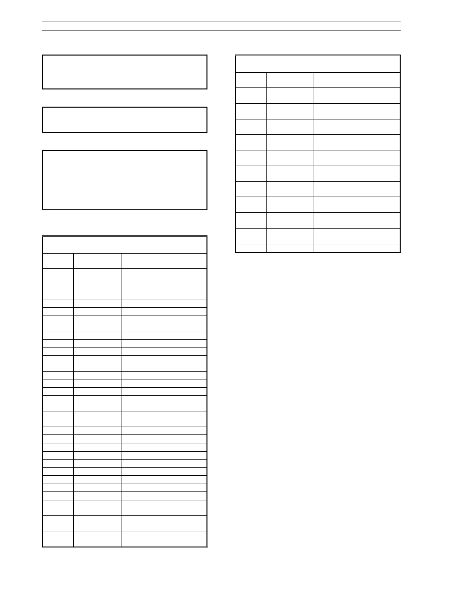
Table B-1. Parts List
Item
Number
Part Number
Description
1
698B235U01
Display Assembly
(Bezel, Display Board,
Front Membrane, and
Gasket)
2
333B016U01
Gasket only
3
173D078U01
Cable Assembly
4
686B736U01
Power Supply - 120/240 V
AC
4
Power Supply - +24 V DC
5
324A528U01
Case - Molded
6
353F064U01
Mounting Bracket only
7
396C272U01
Screw for mounting
bracket
8
090H022U01
Ground Screw
9
172G440U01
Plug - 3P
10
172G440U03
Plug - 12P
11
682A550U01
Single Universal AI3
Module
11
682A550U02
Dual Universal AI3/AI4
Module
12
172F464U04
Plug - 8P
13
172F464U03
Plug - 6P
14
172F464U01
Plug - 4P
15
682A551U01
2DI/2DO Module
16
014F010T10
4-40 x 5/8 Screw
17
172F464U02
Plug - 5P, RS-422/485
17
172F464U07
Plug - 5P, RS-232
18
682A552U01
RS-422/485 Module
18
682A552U02
RS-232 Module
19
014F004T10
4-40 X 1/4 Screw (2 per
module)
20
101W796U01
Retainer (O-Ring - 2 per
module)
21
338F104U01
Identification Tags
(Strip of 3 tags)
Table B-1. Parts List
Item
Number
Part Number
Description
22
355J093U01
Black Mounting Collar -
Single Unit
22
614B836U01
Black Mounting Collar - 2
Unit
22
614B836U02
Black Mounting Collar - 3
Unit
22
614B836U03
Black Mounting Collar - 4
Unit
22
614B836U04
Black Mounting Collar - 5
Unit
22
614B836U05
Black Mounting Collar - 6
Unit
22
614B836U06
Black Mounting Collar - 7
Unit
22
614B836U07
Black Mounting Collar - 8
Unit
22
614B836U08
Black Mounting Collar - 9
Unit
22
614B836U09
Black Mounting Collar - 10
Unit
23
107J013U01
Screwdriver
B.3 Removal and Replacement
Ensure the power is off and disconnect the power
cable plug. Disconnect all cable shield connec-
tions from the ground stud; remove the signal plug
and any option modules from the rear of controller.
A single screw secures the RS-232 or RS-485 mod-
ule to the casework; and the slot A and slot B
option modules are each secured to the casework
with two screws.
The display assembly is secured to the case by
bezel tabs that extend from the assembly into the
case. As shown in Figure B-2, to remove the dis-
play assembly, gently press in the bezel tab with
the screwdriver tip to release it from the case de-
tent, then slide the display assembly forward just
enough so the tab notch is passed the detent. Re-
peat for the remaining four bezel tabs to remove
display assembly from case. Disconnect the cable.
The display assembly must be replaced as a unit
because the display board is staked in place.
Lever latches secure the power supply board inside
the case. Gently pull each lever tab at the back of
the case as the power supply board edge is tilted
passed the lever latch inside the case. The board
comes straight forward out of the case.
Replacement: connect cable to new power supply
board and insert it in case until it is latched. Power
sockets, signal connectors, and ground stud should
be properly aligned with case cut-outs. Connect
53SL6000 Instruction Manual
Appendix B. Maintenance and Parts List
B-2
PARTS