3 auxiliary operator access, 4 operator mode overflow/underflow indication, 4 operator mode overflow/ underflow indication – Micromod Micro-DCI: 53SL6000 Single Loop Controller User Manual
Page 31
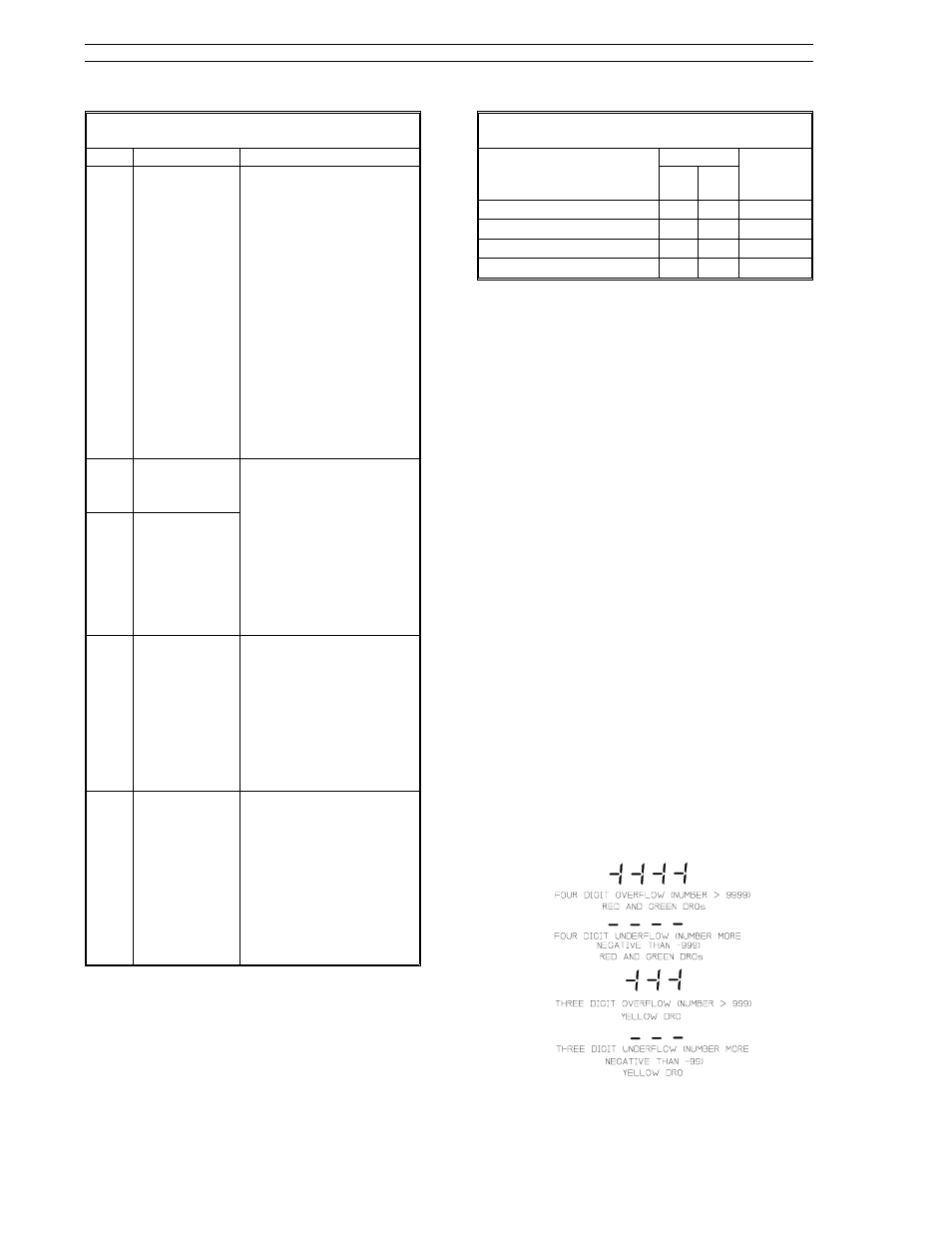
Table 3-1. Operator Mode Display Items
Item
Call-Out
Description
20
Select Mode
and Loop 1/2
Push Button
Pressing this push
button in operator
mode with an active
two loop control
scheme (cASc, L.LiM, or
h.LiM) selects the loop
under display panel
control. It toggles from
one loop to the other
each time it is pressed.
If this push button is
held for three seconds,
it causes engineer
mode to be entered.
Pressing it in engineer
mode causes a return
to operator mode.
21
Loop 1
Select
Indicator
These indicators are for
the two loop control
schemes cASc, L.LiM,
and h.LiM. Either one
of these two indicators
will activate to show
which loop is under
display panel control
as selected by the
Mode push button.
22
Loop 2
Select
Indicator
23
Easy-Tune
Status
This status indicator
blinks during Easy-Tune
operation. A steady-
state-on condition
indicates Easy-Tune
terminated with an
error. It stops blinking
when Easy-Tune
completes successfully.
24
Watchdog
Condition
Indicator
This indicator activates
whenever the
controller detects an
internal processor
failure. When active,
all outputs are forced
to their power-off state.
Attempt to restart the
controller by cycling
power.
Table 3-2. Setpoint Up/Down Push Buttons
Display Panel Action
R/L PB (7)
SPM*
R LED
(8)
L LED
(9)
Alter standard SP value.
Y
Std
No SP control.
Y
Std
Alter standard SP value.
Y
K-SP
Alter ratio SP value.
Y
K-SP
*SPM settings (Std or K-SP) are made in engineer
mode, which is described later in Section 3.
3.3 Auxiliary Operator Access
To facilitate operator access for auxiliary data input
and selected parameter modification, an engineer
mode oPEr menu is provided. This menu allows
display panel entry of logical and analog signal
constants, process variable alarm values, high/low
output limit values, and PID values. It also pro-
vides operator capabilities to execute the Easy-
T u n e s e q u e n c e . A c c e s s t o m e n u i t e m s i s
controlled through the conF-oPr enabling parame-
ters. Because the oPEr menu parameters and their
corresponding conF-oPr enabling parameters are
accessed in engineer mode, they are described in
Tables 3-3 and 3-4, which appear later as part of
the engineer mode information.
3.4 Operator Mode Overflow/
Underflow Indication
Overflow indicators are plus signs (+) and under-
flow indicators are negative signs (-). Illustrations
of the overflow and underflow conditions are pro-
vided in Figure 3-3. They appear in the affected
dro and are decimal point sensitive. If these indica-
tors repeatedly appear, the decimal point should be
repositioned with the conF-cn.1(cn.2)-dP parame-
ter described in Table 7-3. Adjusting this parame-
ter requires knowledge of engineer mode, which is
described next in this section.
Figure 3-3. Overflow/Underflow Indicators
53SL6000 Instruction Manual
Section 3. Display Panel
3-4