5 discrete inputs, 6 discrete outputs – Micromod Micro-DCI: 53SL6000 Single Loop Controller User Manual
Page 49
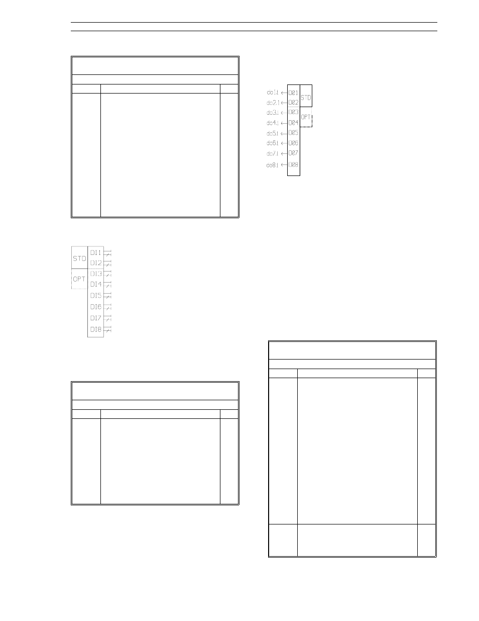
Table 5-10. Analog Output Registers
(ProG Menu
→ Ao Module)
Prompt
Description
Dft
Ao1.i
Ao2.i
Ao3.i
(cont)
Analog Output Connections (cont)
Specifies the input connections for
the standard analog output Ao1
and analog outputs Ao2 and Ao3.
Input selections are as follows:
Ai8: Analog input 8.
Fnc: Function module output.
SP: Control scheme setpoint
output value
PV: Control scheme PV output
value
dV: Control scheme deviation
output value.
out: Control scheme calculated PID
value or manual push button
value.
out
nc
nc
5.5 Discrete Inputs
There are eight discrete input data-
base locations (di1 - di8). Each of
the eight discrete inputs present
both, the standard and inverted val-
ues. Standard inputs at di1 and di2,
and optional inputs di3 and di4 (if the
2DI/2DO option is installed), reflect
logic values based on the voltage
applied as stated in Table 5-11. Dis-
crete inputs which are not associ-
ated with hardware are available for
network or operator input. Discrete
inputs di7 and di8 are accessable to the operator
via enabled oPEr-oPr-di7 and oPEr-oPr-di8 pa-
rameters.
Table 5-11. Discrete Input Selections
(ProG Menu
→ di Module)
Prompt
Description
Dft
di1,
di8
Discrete Input
State = 1 when signal is a low
voltage (0 to 1 V dc) or closed
contact. A low voltage input
causes the output to be true (1) and
the inverted output (/) to be a 0.
State = 0 when signal is a high
voltage (4 to 24 V dc) or open
contact. A high voltage input
causes the outputs to false (0) and
the inverted output (/) to be a 1.
0
5.6 Discrete Outputs
There are eight discrete output data-
base locations (do1 - do8). Standard
outputs do1 and do2 and optional
outputs do3 and do4 (if the 2DI/2DO
option is installed) produce external
contact actions in response to the
values of the discrete outputs. Dis-
crete outputs not associated with
hardware can be accessed by the
network. The values stored in dis-
crete outputs d07 and do8 can be
looped-back if selected by the path parameters of
the characterizer, math function block, or logic
blocks 1 and 2 (only do8 for the logic blocks).
If the 2DI/2DO option module is installed, it loads
its status identification code in the conF-SYS-oPtb
parameter, as described in Table 5-13. The
2DI/2DO module plugs into the rear of the control-
ler at the option slot B connector and is secured to
the case with two screws. (See Figure 2-9.)
A typical use of a discrete output is to trigger an
annunciator horn at the onset of a process variable
alarm.
Table 5-12 lists the parameters contained in the
discrete output block.
Table 5-12. Discrete Output Selections
(ProG Menu
→ do Module)
Prompt
Description
Dft
do1.i
do2.i
do3.i
do4.i
do5.i
do6.i
do7.i
do8.i
Digital Output Connections
Specifies the input connections for
digital outputs do1 - do8. Input
selections are as follows:
nc: No connection.
PA1: cn.1 PL1 active.
PA2: cn.1 PL2 active.
Vup: Time proportional, three step
up.
Vdn: . Three step down.
PA1.2: cn.2 PL1 active.
PA2.2: cn.2 PL2 active.
Fnc: Math function block digital
output.
chr: Characterizer digital output.
LG1: Logic block 1 output.
LG2: Logic block 2 output.
LG3: Logic block 3 output.
LG4: Logic block 4 output.
PA1
PA2
VuP
Vdn
nc
nc
nc
nc
do1-
do8
Discrete Output
It is the state value to be applied to
the output as specified by
inV1- inV8.
0
Section 5. Inputs/Outputs (I/O)
53SL6000 Instruction Manual
5-5