Appendix c: datalink protocol, C.1 overview, C.2 configuring the system module for datalink – Micromod Micro-DCI: 53SL6000 Single Loop Controller User Manual
Page 124: C.3 protocol
C.1 Overview
Thirty-two addressable controllers (0-31) can be
connected to a datalink for information transfer
to/from a host, which initiates all transactions.
This section provides information to configure the
system module (prompts iA, bAUd, dLP, dLS, and
dLE), a description of the datalink protocol mes-
sage field definitions, a summary table of the con-
t r o l l e r m e m o r y a d d r e s s s c h e m e , a n d a
mnemonic-datapoint cross reference table
unit-tag
•
atom transfers.
C.2 Configuring the System
Module for Datalink
To initiate the controller for datalink communica-
tions, respond to the system module prompts with
new values/selections if the default (Dft) settings
shown in Table C-1 requires changing.
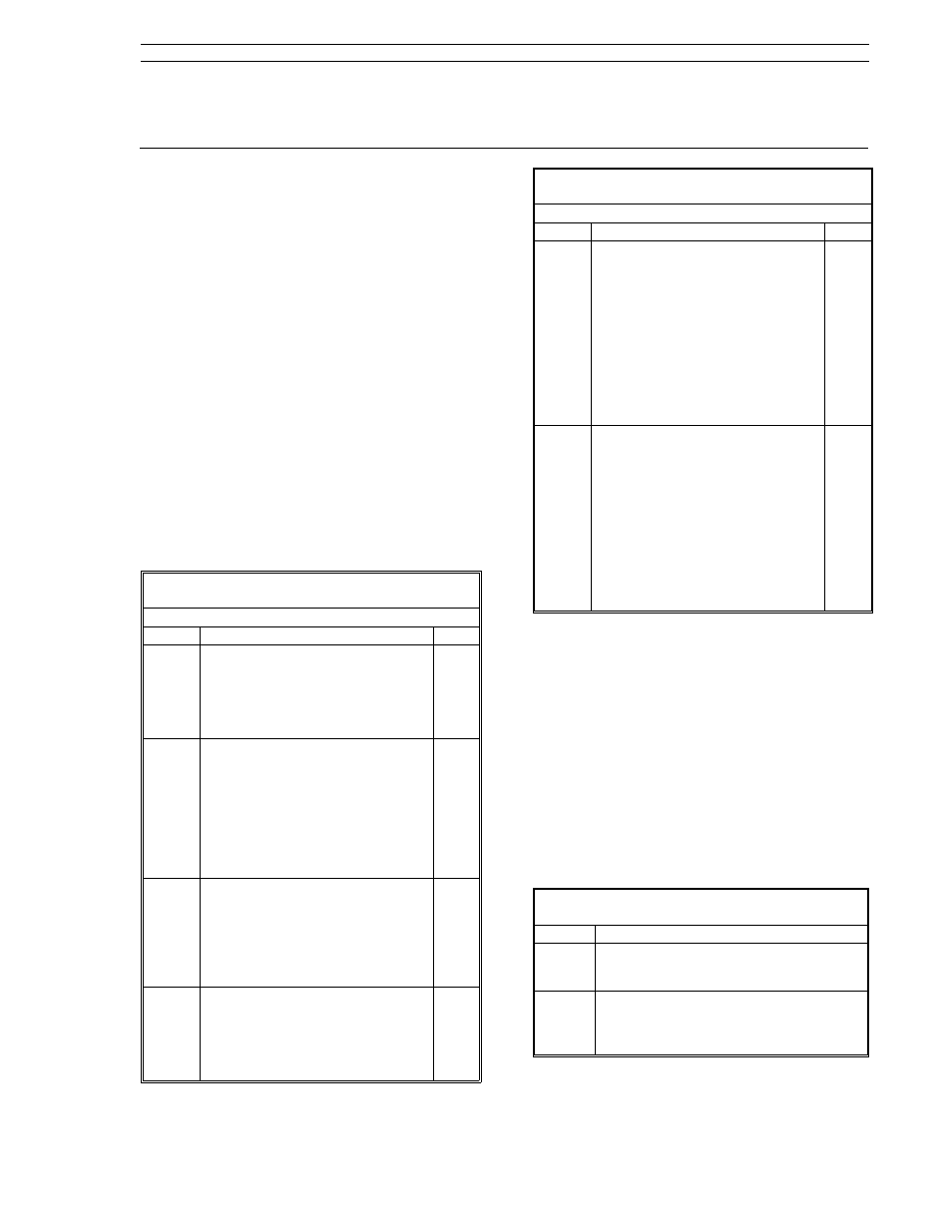
Table C-1. System (SYS) Prompts (Datalink)
(conF Menu
→ SYS Module)
Prompt
Description
Dft
iA
Instrument Addrsss
It is the address assigned to this
controller on the datalink. Valid
addresses are from 0 - 31. No two
controllers can have the same
address on the datalink.
0
bAUd
Baud Rate
This value is set to match the data
transfer rate of the datalink. Valid
menu selections are:
110
4800
300
9600
600
19.2K
1200
14.4K
2400
28.8K
9600
dLE
Datalink Enable
Selections are as follows:
on: Allows controller datalink
communication.
oFF: The controller is not permitted
to communicate over the
datalink.
on
dLP
Datalink Parity
Selections are as follows:
on: It indicates parity generation
and checking for even parity
serial byte protocol is enabled.
oFF: It indicates no parity protocol.
on
Table C-1. System (SYS) Prompts (Datalink)
(conF Menu
→ SYS Module)
Prompt
Description
Dft
dLS
Datalink Stuffing
Selections are as follows:
on: Selects F&P byte stuffing which
inserts a NULL (00) byte after
every SOH (7E hex) that is not
the beginning of a message.
This permits user written
communications software to
determine the number of bytes
to expect in a response
message.
oFF: Disables datalink stuffing.
on
tAG
Tag Name
Allows a 10 character datalink tag
to be assigned to the controller.
Four characters maximum can be
displayed at any one time. Using
the engineer mode shift right push
button, the ten character positions
are displayed as follows:
0123
→ 3456 → 6789
Characters are selected for each
position with the scroll
forward/backward push buttons.
C.3 Protocol
The datalink protocol requires the host to initiate all
transactions. There are two basic categories for all
of the datalink message types: interrogate, which
is used to read data from an addressed controller,
and change, which is used to alter a value in an
addressed controller. The addressed controller de-
codes the message and provides an appropriate
response. The protocol message field definitions
are provided in Table C- 2.
Table C-2. Datalink Protocol
Symbol
Description
SOH
Start of Header
This character, 7E, denotes the beginning
of a message.
I.A.
Instrument Address
The address of the controller responding
to the transaction. It must be within a
range of 00-1F (00-31 decimal).
Appendix C: Datalink Protocol
Appendix C. Datalink Protocol
53SL6000 Instruction Manual
C-1