6 control scheme parameters – Micromod Micro-DCI: 53SL6000 Single Loop Controller User Manual
Page 82
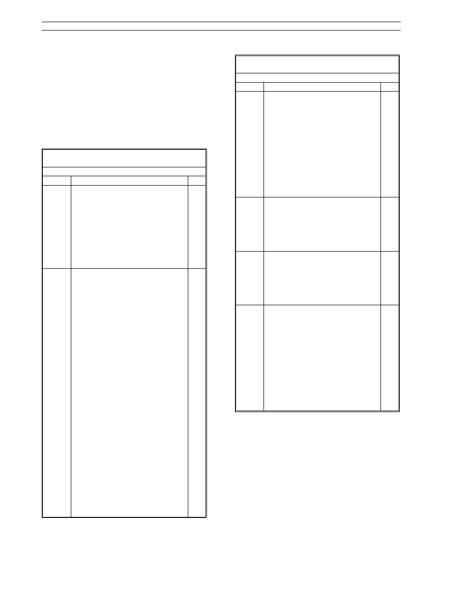
7.6 Control Scheme Parameters
Table 7-2 provides the control scheme ProG-cS
module parameters. These parameters set the ba-
sic operation of the control scheme block and de-
termine the input signal sources. Whenever these
parameters are edited, control operation is turned
off as when any other ProG menu parameter is
edited.
Table 7-2. Control Scheme Parameters
(ProG Menu
→ cS Module)
Prompt
Description
Dft
SchM
Control Scheme
This is a mode switch used to select
the control scheme. Control
scheme selections are as follows:
SnGL:
Single loop control.
cASc:
Cascade control.
L.LiM:
Low limiter (high override)
control.
h.LiM:
High limiter (low override)
control.
in.Ld:
Indicator/Loader operation.
SnGL
cS.A
cS.b
cS.c
cS.d
cS.E
cS.F
Control Scheme cS.A - cS.F Input
s
Specifies connections to the cS.A -
cS.F inputs of the control scheme.
Input selections are as follows:
0:
A constant value input of 0.0.
Ai1:
The standard analog input 1
value or a constant value
previously loaded into the Ai1
register.
Ai2:
The standard analog input 2
value or a constant value
previously loaded into the Ai2
register.
Ai3:
The optional analog input 3
value or a constant value
previously loaded into the Ai3
register.
Ai4:
The optional analog input 4
value or a constant value
previously loaded into the Ai4
register.
Ai5:
A constant value previously
loaded into this register.
Ai6:
A constant value previously
loaded into this register.
Ai7:
A constant value previously
loaded into this register.
Ai8:
A constant value previously
loaded into this register.
A03:
Looped-back value from A03
register.
Fnc:
The function generator
analog output.
Ai1
Ai2
0.0
Ai7
0.0
0.0
Table 7-2. Control Scheme Parameters
(ProG Menu
→ cS Module)
Prompt
Description
Dft
PVt
Process Variable Tracking
Specifies whether the setpoint
should be forced to match the
current process variable cS.A input
when loop 1 is not in automatic
control. When PVt is set to YES, the
setpoint automatically tracks the
process variable whenever loop 1 is
in manual or forced output
operating mode (output tracking).
Process variable tracking eliminates
process bumps when switching to
automatic from manual or forced
output (output tracking) operation.
no
doFb
Digital Output Feedback
When set to YES, it enables the
valve position value from the slide
wire to be displayed in the yellow
dro. This parameter is applicable for
proportional speed floating control
output.
no
EXrF
External Reset Feedback
When set to YES, the PID reset value
comes from an external source via
the control scheme cS.E input.
When set to no, the PID reset value
is feedback from the control
scheme output.
no
PVt.2
Process Variable Tracking 2
Specifies whether the setpoint
should be forced to match the
current process variable cS.b input
when loop 2 is not in automatic
control. When PVt.2 is set to YES,
the setpoint automatically tracks
the process variable whenever loop
2 is in manual or forced output
operating mode (output tracking).
Process variable tracking eliminates
process bumps when switching to
automatic from manual or forced
output (output tracking) operation.
no
53SL6000 Instruction Manual
Section 7. Control Scheme Block
7-24