8 rs-232 & rs-485 modules, 9 applying power – Micromod Micro-DCI: 53SL6000 Single Loop Controller User Manual
Page 26
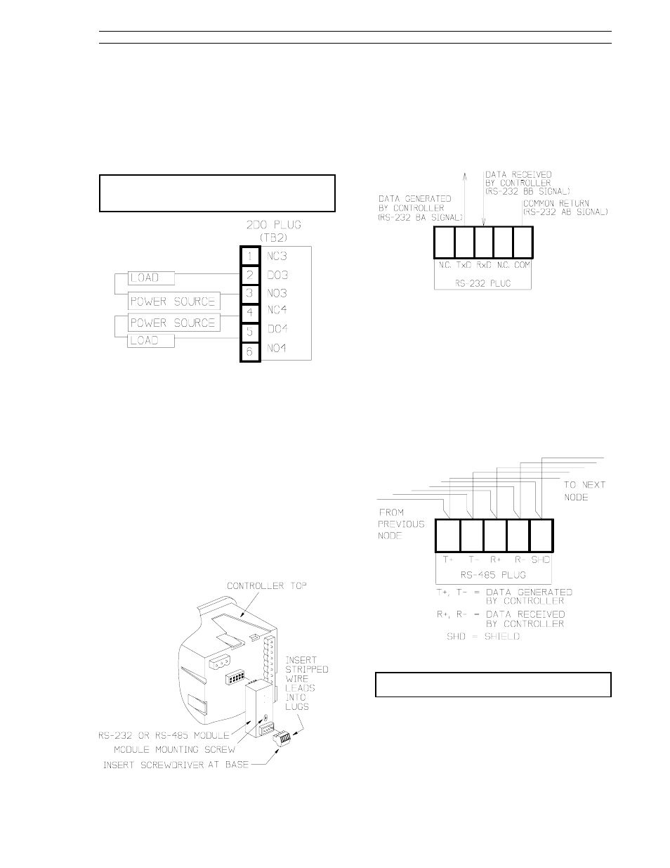
Signal input connections for the 2DO six terminal
plug are illustrated in Figure 2-11. Both, DO1 and
DO2 are Form C relays. The contact load capaci-
ties are 250 V ac or 250 V dc maximum switching
voltage; 5 A switching current; 1250 VA-ac maxi-
mum, and 30 W at 250 V-DC maximum or 100 W at
24 V-DC maximum switching power.
NOTE: The 2DI/2DO module provides line
suppression; appropriate load suppression must
be supplied by the user.
Figure 2-11. 2DO Plug Connections
2.8 RS-232 and RS-485 Modules
This information applies to only those controllers
with the optional RS-232 module or RS-485 mod-
ule.
Figure 2-12 illustrates the RS-232 module or the
RS-485 module location on the controller back-
plane. The module is socket mounted and is se-
cured to the backplane with a screw. Also shown in
Figure 2-12 is the module signal plug, which is
keyed to prevent inverted insertion in its socket.
As shown in Figure 2-12 (e.g., INSERT SCREW-
DRIVER AT BASE), the lug adjusting screws are
accessed at the bottom of the plug.
Figure 2-12. RS-232 or RS-485 Module
2.8.1 RS-232 Plug Connections
Signal connections to the RS-232 module plug are
illustrated in Figure 2-13. Transmitted (TxD) and
received (RxD) signals are with respect to the con-
troller.
Figure 2-13. RS-232 Plug Connections
2.8.2 RS-485 Plug Connections
Signal connections to the RS-485 module plug are
illustrated in Figure 2-14. In the illustration, the
controller is shown wired as a drop on the datalink.
Two wires are therefore connected to each lug:
one set (T+, T-, R+, R-, SC) that comes from the
previous node and another set that is connected to
the next datalink node.
Figure 2-14. RS-485 Plug Connections
NOTE: Cable shield should be connected to
ground at only one location.
2.9 Applying Power
Verify all controller connections and ensure each
connection is mechanically sound before closing
the power switch to apply controller power. The
Section 2. Installation and Power-Up Procedures
53SL6000 Instruction Manual
2-7