Safety symbols – B&K Precision 2516 - Manual User Manual
Page 7
7
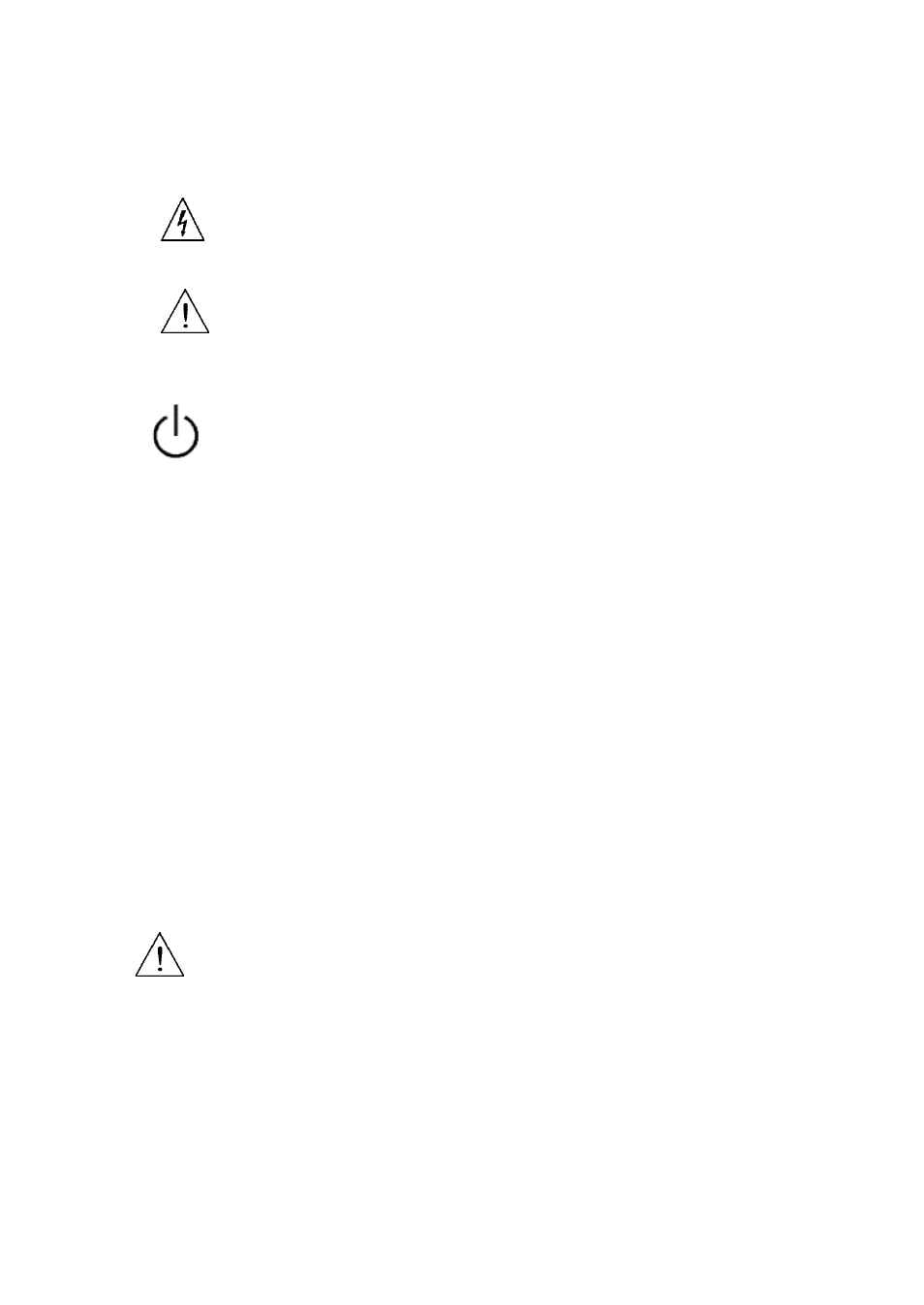
Safety Symbols
Electrical Shock hazard.
Refer to the operating user manual for warning information to
avoid hazard or personal injury and prevent damage to
instrument.
This symbol shows that the switch is a power switch located at
the front panel. Pressing this button turns on the oscilloscope,
and holding it down for a few seconds turns off the
oscilloscope.
CATI
CATII
Category I overvoltage conditions.
Measurement instruments whose measurement inputs are
not intended to be connected to the mains supply. The
voltages in the environment are typically derived from a
limited-energy transformer or a battery.
Category II overvoltage conditions.
Measurement instruments whose measurement inputs are
meant to be connected to the mains supply at a standard wall
outlet or similar sources.
CATIII
Category III overvoltage conditions.
Measurement instruments whose measurement inputs are
meant to be connected to the mains installation of a building.
Maximum Input Voltages
Oscilloscope Inputs
Maximum input voltage to CH1 and CH2 BNC direct(1:1) - CATII 300V
RMS, CATI 150V RMS
Maximum input voltage to CH1 and CH2 BNC via 10:1 probe PR250SA
(included with models 2515 and 2516) - CATII 1000V RMS, CATIII 600V
RMS