Using trend plot, Figure 71 - connection for capacitance measurement, 7 using trend plot – B&K Precision 2516 - Manual User Manual
Page 124
124
CAUTION:
Always connect the test leads to the instrument
inputs first before connecting the DUT to avoid
potential shock hazard.
NOTE:
The capacitance measurement function is used for
measuring general purpose electrolytic capacitors.
Follow these steps to make a capacitance measurement.
4.
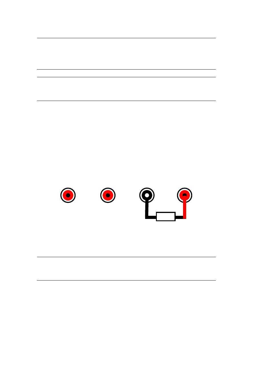
Connect the black test lead to the COM input. This will connect to
the negative side of your capacitor.
5.
Connect the red test lead to the V.Ω.C input. This will connect to
the positive side of your capacitor.
6.
Probe with the test leads to the DUT and take the measured reading
on display.
Figure 71 - Connection for Capacitance Measurement
WARNING:
Do not apply more than 1000 VDC across the
terminals or they will be damaged.
4.7 Using Trend Plot
The trend plot function is available for some of the multimeter
measurement functions. For details on using trend plot, refer to “Meter
Trend Plot” in the following chapter.
10 A
mA
COM
V.Ω.C
Capacitor