Figure 69 - connection for continuity test – B&K Precision 2516 - Manual User Manual
Page 122
122
WARNING:
Fully discharge the capacitor before connecting it
to any of the inputs or it may damage the
instrument.
CAUTION:
Always connect the test leads to the instrument
inputs first before connecting the DUT to avoid
potential shock hazard.
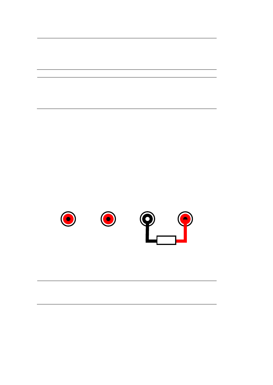
To setup for continuity testing, do the following:
1.
Connect the black test lead to the COM input.
2.
Connect the red test lead to the V.Ω.C input.
3.
Connect the two leads together to verify that the continuity function
is working properly. The instrument should have a continuous beep
sound.
4.
Probe with the test leads to the DUT and take the measured reading
on display.
5.
If continuity is good, it will have a continuous beep sound.
Figure 69 - Connection for Continuity Test
WARNING:
Do not apply more than 1000 VDC across the
terminals or they will be damaged.
10 A
mA
COM
V.Ω.C
Continuity