6 acceptance testing – GE Industrial Solutions CPS6000-M2 User Manual
Page 89
CPS6000-M2 Installation Guide H5694720
Issue 8 January 2008
89
6 Acceptance Testing
NOTE: The controller may report a limited recharge alarm during these tests.
NOTE: At any time you encounter difficulty with these steps, refer to the Troubleshooting
Section.
Communication with Rectifiers and Converters
Step
Action
1
Place external battery disconnect switches in the ON (connected) position if equipped.
2
Turn on all ac circuit breakers supplying rectifiers.
3
Adjust the contrast (if needed) for the site’s ambient condition by using the up and down
arrow keys at the Main Menu. Contrast adjust is also available at :
MENU > CONFIGURATION > SYSTEM SETTINGS > DISPLAY CONTRAST.
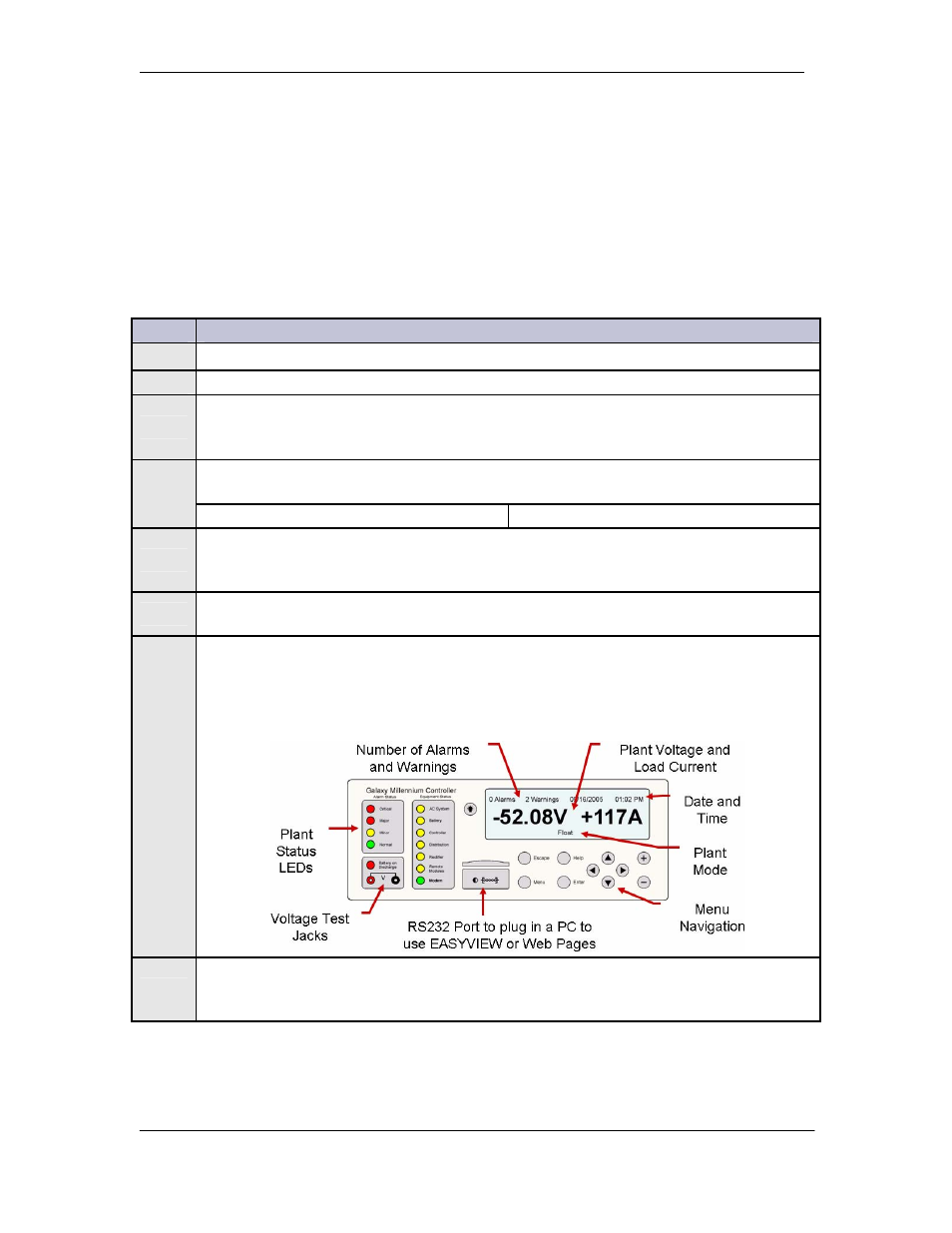
After approximately 30 seconds, are all lit LEDs on all components including
rectifiers, the controller, LVD control boards, and Aux Displays green?
Yes – Go to Step 7.
No – Proceed to Step 4.
4
Initiate the “Clear Events” and “Uninstall Equipment” operations found under MENU
> CONTROL / OPERATIONS menu. Reference to Appendix A: Pulsar Controller
User Interface as needed.
5
If the controller appears not to be powered or not responsive, remove and reseat the
controller.
6
If all lit LEDs still aren’t green, review the installation procedure or refer to the
Troubleshooting section in this manual. The controller display should indicate “0
ALARMS”. The system float voltage, total load current, and system operating mode
should be observable as indicated for no alarms and the system rectifier voltage should
be displayed.
7
If Slope Thermal Compensation (STC) is active, turn off STC by disconnecting and
reconnecting the probes. An alarm may occur, and will retire when the probes are
reconnected.