Installing qs873 vt battery probes – GE Industrial Solutions CPS6000-M2 User Manual
Page 62
CPS6000-M2 Installation Guide H5694720
Issue 8 January 2008
62
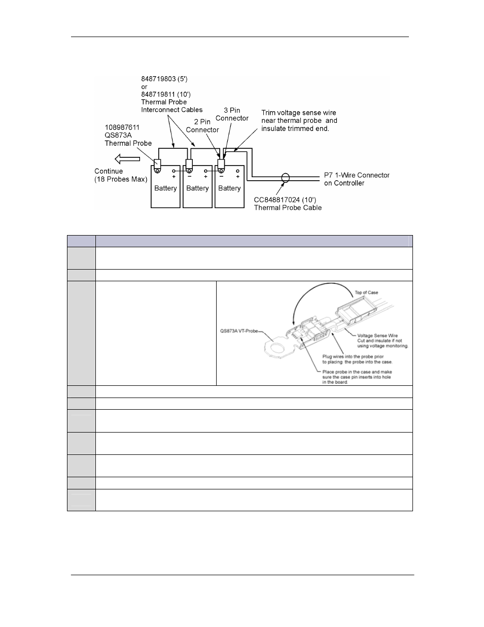
Installing QS873 VT Battery Probes
Step
Action
1
Insert the RJ-45 end of the CC848817024 wireset into the P7 1-wire connector on the
controller.
2
Cut the brown voltage sense wire on the CC848817024 at the 3-pin connector.
3
QS873 probe provides 2-pin
and 3-pin receptacles and a 1/4-
inch ring terminal.
Insert the 3-pin connector end
into the receptacle on the
closest VT-Probe.
4
Snap the cover closed on the VT-probe.
5
Place the first probe to the battery post (as in the battery string picture above).
6
Verify the number of probes (1) registered with the controller with command:
MENU →STATUS → BATTERIES → NUM TEMP PROBES.
7
Connect either the 848719803 (5-ft) or the 848719811 (10-ft) cable to the 2-position
receptacle of the first probe and to the 3-position receptacle of another probe.
8
Verify the number of probes (2) registered with the controller with command:
MENU → STATUS → BATTERIES →NUM TEMP PROBES.
9
Repeat Steps 7-8 for each probe until all probes are installed.
10
When all probes are installed, verify they are connected and operating with command:
MENU → STATUS → BATTERIES → NUM TEMP PROBES.
The controller is now set to make thermal measurements in performing slope thermal
compensation. Additional parameters may be set on the controller to customize this feature.