GE Industrial Solutions CPS6000-M2 User Manual
Page 49
CPS6000-M2 Installation Guide H5694720
Issue 8 January 2008
49
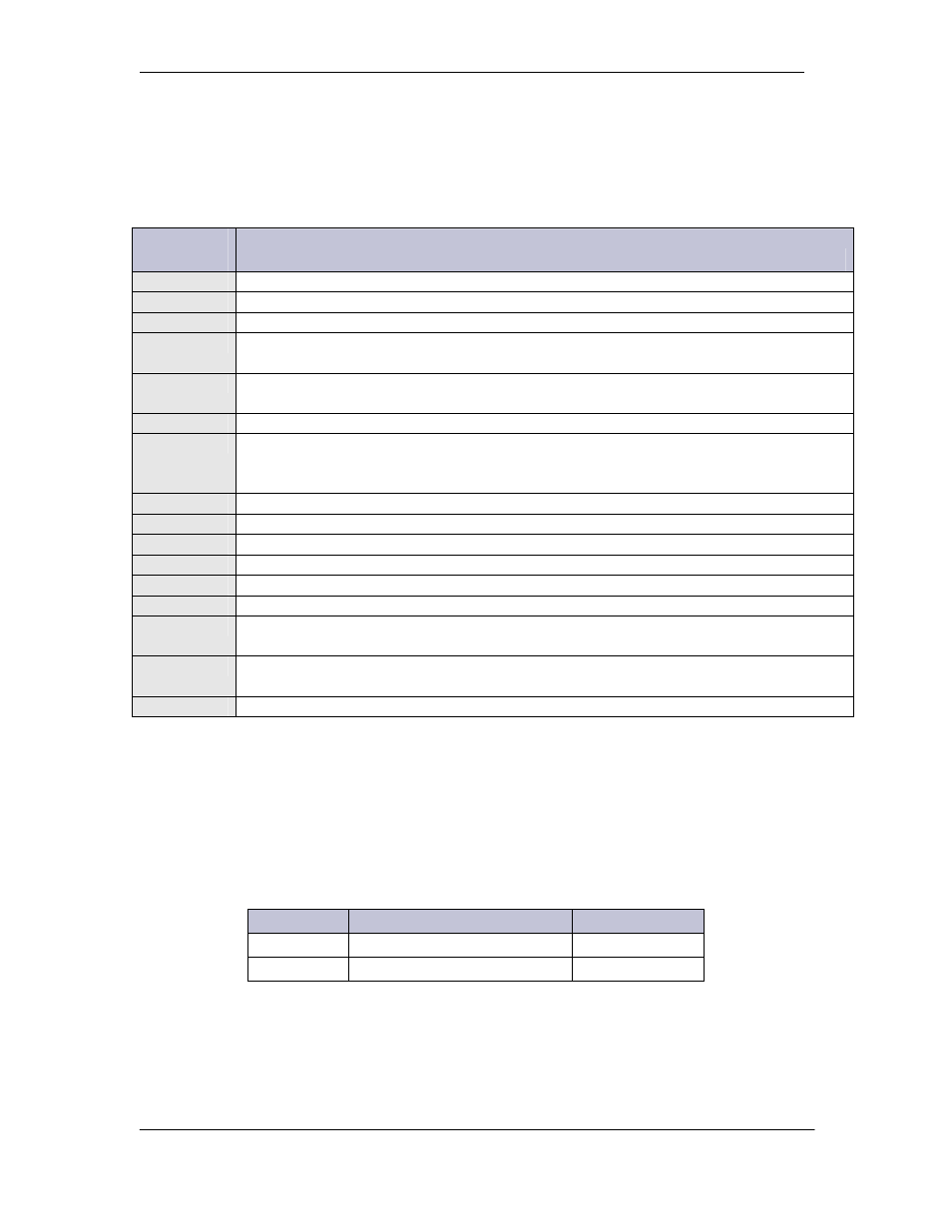
The MCR1/MCR1B control board contains the connections for all the input and outputs. The
following table provides a list of the connections with their respective reference designators and
brief description of the particular connection.
Interface
Reference
Description
P1
Connectorized interface for large parallel format 8x40 LCD assembly
P2
10/100 Base-T LAN/Ethernet interface
P3
Connectorized interface for 10K/30K thermistor probe options or 210E
P6
Connectorized input for input power, monitoring of two shunts, plant sense voltage,
and Major Fuse alarm (Same connection as on the Millennium)
P7
RJ45 receptacle for ground referenced Auxiliary RS485 circuit and One-Wire
monitoring devices
P8
BSL1-4 circuit pack Interface connector for Input/Output to controller
P9
RJ45 receptacle for isolated RS485 system component monitoring and control of
rectifiers, converters, low voltage disconnect contactors, and bay level alarm inputs
(Serial Rectifier bus)
P13
Factory test connector (not used in the field)
P14
Connectorized interface for future smaller serial format LCD
P15
Connectorized interface for future smaller serial format LCD
P201
Connectorized interface for optional Modem
P202
Ground referenced DB-9 for local RS232 serial port
P205
Option board connector
TB1
Terminal block interface for RS232/RS485 Auxiliary port and Remote Peripheral
Module (RPM) connections
TB2
Terminal block interface for three additional 10K thermistor probe or 210E connection
options
J10
USB interface (reserved for future use)
Fuses
Two Fuses, located on the MCR1/MCR1B board, provide protection for the controller input
power and Alarm Battery Supply (ABS). ABS is used to power alarm panels or other devices
requiring the power system voltage at no more than 1.3A.
Fuse
Description
Fuse Size
F1
Controller Input Power
3A
F2
Alarm Battery Supply (ABS)
1.3A