Installing qs-series ringers – GE Industrial Solutions CPS6000-M2 User Manual
Page 46
CPS6000-M2 Installation Guide H5694720
Issue 8 January 2008
46
Installing QS-Series Ringers
Step
Action
1
• Up to two Ringer Chassis’s may be installed per rectifier shelf, one in each of the two
right-most power slots. Each Ringer chassis accepts up to two ringer modules, a
primary and a spare.
• For redundant ringing, install both Primary and Spare Ringers in each Ringer Chassis.
WARNING: Consider the Ring signal as hazardous voltage. When
rectifiers and/or battery power is present, all installed QS820M ringer
chassis and QS820A ringer modules will be powered.
• Note: Ringer output connections are made after ringers are seated in the Ringer
chassis.
• Note: The primary and spare Ringer modules install facing opposite directions. No
rectifiers may be installed to the right of a Ringer Chassis. Slots dedicated to Ringers
do not require an ac input circuit in the AC Termination Panel
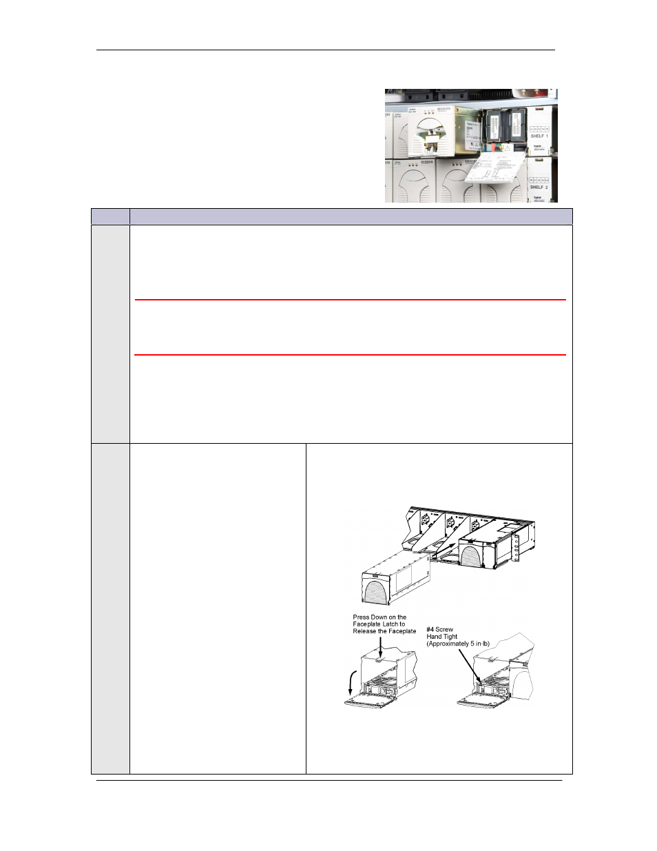
2
• Slide the ringer chassis into
the power slot.
• Press firmly until the
connector on the rear of the
ringer chassis engages with
the connector at the back of
the power slot on the shelf.
• Verify the hook under the
front left of the ringer chassis
hooks under the shelf.
• Press down on the faceplate
latch and open the faceplate.
• Secure the ringer chassis to
the shelf using one #4 screw,
hand tight to approximately 5
in-lbs.
• Repeat if a second ringer
chassis is required.