GE Industrial Solutions CPS6000-M2 User Manual
Page 57
CPS6000-M2 Installation Guide H5694720
Issue 8 January 2008
57
Remote Peripheral Monitoring (RPM)
Monitoring modules available consist of:
• 221F -50-150mV Shunt monitors (6 channels + 1 temperature channel)
• 221J 0-100mV DC Voltage transducer monitors (6 channels + 1 temperature channel)
• 221A 0-3V DC Voltage monitors (6 channels + 1 temperature channel)
• 221B 0-16V DC Voltage monitors (6 channels + 1 temperature channel)
• 221C 0-70V DC Voltage monitors (6 channels + 1 temperature channel)
• 221D 0-200V DC Voltage monitors (6 channels + 1 temperature channel)
• 222A Binary Input monitor (6 channels + 1 temperature channel)
• 223T Temperature monitor (7 Channels)
• 214A Control Relay module (3 sets of programmable form C relay outputs)
The user may connect a maximum of 95 of any combination of these modules serially.
Step
Action
NOTE:
This section only describes a single module connection to the controller. Modules
MUST BE PROGRAMMED after they have been installed or they may not function
properly. Detailed connection and configuration information may be found in the
RPM Product Manual 167-790-063.
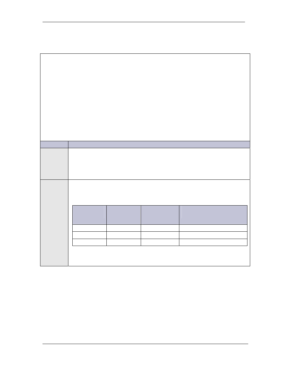
1
Using RPM bus cable (comcode 407377704), wrap the cable through the EMI
inductor bead twice. Place the bead approximately 3 inches from the controller.
Connect the bus cable to TB-1 on Millennium and TB101 on the RPM
TB-1 Pin
Assignments
TB-1 Pin
Descriptions
RPM
Conductor
Color
RPM Conductor
Description
6
*6
Blue or White
Power/Communications
8
*8
Blue or White
Power/Communications
9 or 10
FGND
Bare wire
Shield
*connections of the bus wire are NOT polarity sensitive.