GE Industrial Solutions CPS6000-M2 User Manual
Page 101
CPS6000-M2 Installation Guide H5694720
Issue 8 January 2008
101
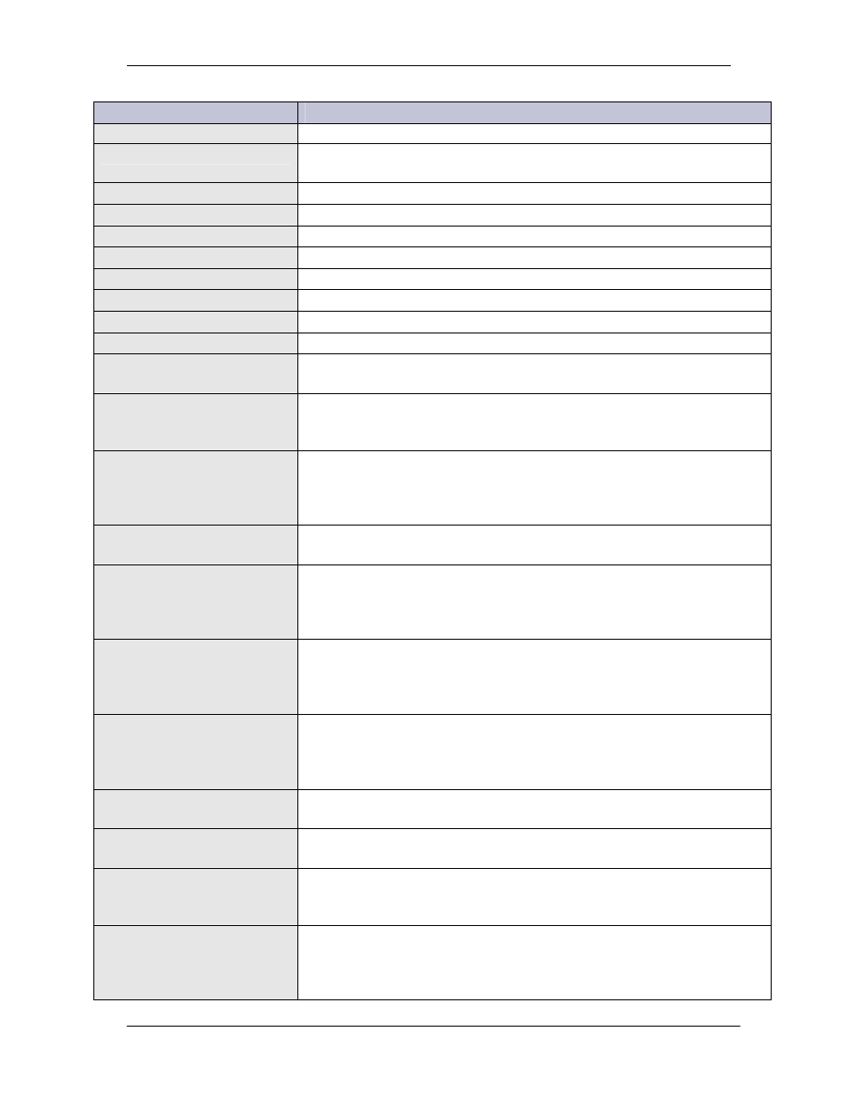
Alarm Description
Explanation
as that of a previously installed converter.
Connected Equip Alarm 1
Equipment monitored by Galaxy through Data Switch Port-1 is reporting
an alarm.
Connected Equip Alarm 2
Equipment monitored thru Data Switch Port-2 is reporting an alarm.
Connected Equip Alarm 3
Equipment monitored thru Data Switch Port-3 is reporting an alarm.
Connected Equip Alarm 4
Equipment monitored thru Data Switch Port-4 is reporting an alarm.
Connected Equip Alarm 5
Equipment monitored thru Data Switch Port-5 is reporting an alarm.
Connected Equip Alarm 6
Equipment monitored thru Data Switch Port-6 is reporting an alarm.
Converter Fail
A converter connected to the serial bus has failed.
Converter Fan Major
More than 1 converter fan has failed.
Converter Fan Minor
A single converter fan has failed.
Clock Changed
A change has been made to the Time or Date setting. This is a latched
event, remaining active until cleared by a user.
Rectifier Current Limit
The rectifiers connected to the controller’s serial bus have reached their
current limit setting. Plant voltage may, therefore, be lower than that
requested in Rectifier Manager.
Minor Comm Fail Alarm
The controller has lost communication with a device that it had
previously recognized on its rectifier/converter serial bus. If one of these
devices is to be permanently removed, it is necessary to issue a
UNINSTALL DEVICES command to clear the alarm.
Multiple Converter Fail
Multiple converters connected to the controller’s serial bus have failed.
This threshold is programmable.
Contactor 1 Failed
A contactor controlled by the controller’s LVD settings (usually used
with all LVBD contactors of a plant) is in the opposite state of that it has
been instructed to be in (open if instructed to be closed, closed if
instructed to be open).
Contactor 2 Failed
A contactor controlled by the controller’s LVD settings (usually used
with all LVBD contactors of a plant) is in the opposite state of that it has
been instructed to be in (open if instructed to be closed, closed if
instructed to be open).
Contactor 3 Failed
A contactor controlled by the controller’s LVD settings (sometimes used
with some of the LVLD contactors of a plant) is in the opposite state of
that it has been instructed to be in (open if instructed to be closed, closed
if instructed to be open).
Contactor 1 Open
The contactors controlled by the controller’s LVD settings (usually used
with all LVBD contactors of a plant) are open (disconnected).
Contactor 2 Open
The contactors controlled by the controller’s LVD settings (usually used
with some or all LVLD contactors of a plant) are open (disconnected).
Contactor 3 Open
The contactors controlled by the controller’s LVD settings (sometimes
used with some of the LVLD contactors of a plant) are open
(disconnected).
Queue Overflow
The 256 event call-out on alarm memory queue filled, causing events
occurring while full to be dropped from the call-out queue. This is a
latched event, remaining active until cleared by a user. Usually indicates
that programmed phone numbers are not responding.