6 testing ai in “current” mode, 7 testing rtd module, Testing ai in “current” mode – B&B Electronics ZZ24D-NA(NB,NC,ND)-SR - Manual User Manual
Page 74: Testing rtd module
Troubleshooting
68
Manual Documentation Number: pn7515_ZlinxIO-0712m
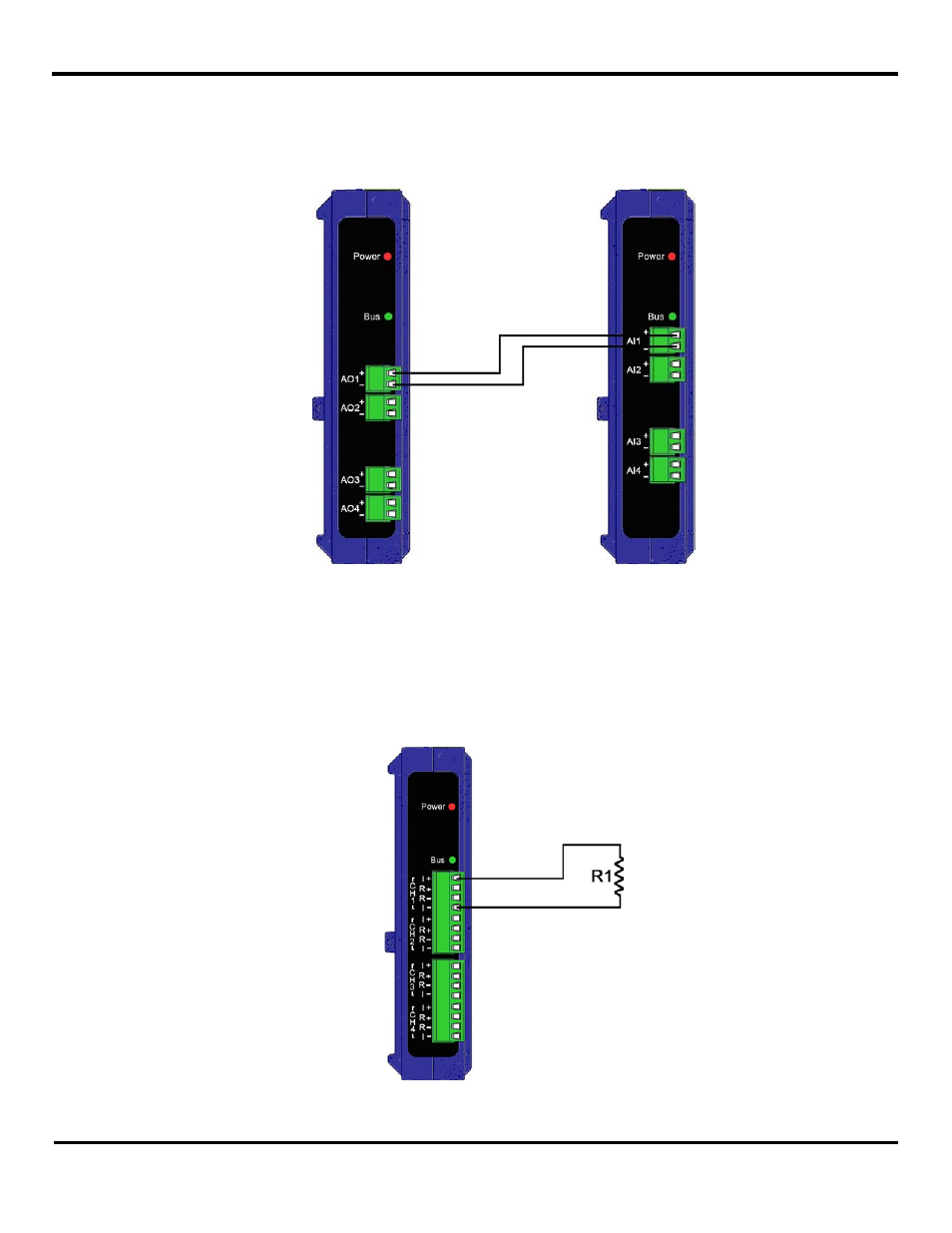
9.1.6 Testing AI in “Current” Mode
To check an AI configured in “Current” mode use a ZZ-4AO-2 module (sourcing AO) as a source of current for the analog input
module (see Figure 50). Both modules need to be in current mode. Set the system up as a Modbus system with two unique
Modbus addresses. Set an output value for the ZZ-4AO-2 device and then read the input value on the corresponding analog
input module that is being tested. It should match the output value that was set for the ZZ-4AO-2 module.
Figure 50 Providing the current signal for the Analog Input wiring with help of the ZZ-4AO-2
9.1.7 Testing RTD module
Connect two wires (I+ and I-) on System-1 to a resistor with known nominal values, for example 100
Ω for Pt100, 1000Ω for
Pt1000, and 10
Ω for Cu 10. These values correspond to ~ 0 degree C. (see Figure 51). In the Zlinx I/O Configuration choose
the following configuration setting: Peer-to-Peer mode, 2-wire mode, Pt100 connection (if using 100
Ω input). Connect a
voltmeter to the corresponding AO on System-2. To verify the output voltage you will need to convert the ~ 0ºC input to a
voltage. To do this you can refer to Appendix F: RTD Module.
Figure 51 RTD (2-wire) connection diagram