B&B Electronics ZZ24D-NA(NB,NC,ND)-SR - Manual User Manual
Page 50
Configuration & Operation
44
Manual Documentation Number: pn7515_ZlinxIO-0712m
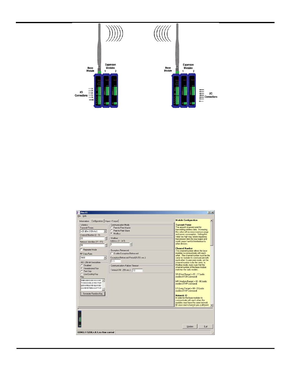
Figure 367 Modbus Mode
Digital and analog signals applied to the Zlinx Wireless I/O module’s input terminals are converted to Modbus messages to be
sent back to the radio modem. Digital Inputs are stored as 1nnnn (coil) addresses; Analog Inputs are converted to 12 bit
binary values and stored in 3nnnn (input register) addresses.
To configure the Zlinx Wireless I/O for Modbus mode:
1. Select the Configuration tab.
2. Select the Modbus option button.
3. In the Modbus Address box, type the Modbus address to be used.
The allowable range of Modbus addresses is from 1 to 247. The default Modbus address is 1.
4. Set the value for the Communication failure timeout (in seconds). If within the predefined timeframe no data is coming
from Modbus Master (Modbus Radio Modem), the Zlinx I/O device perceives it as a communication failure
Figure 378 Configuration Tab (Default values are with encryption disabled and maximum radio power)
- USOPTL4DR-LS - Datasheet (2 pages)
- ZXT9-IOA-KIT - Manual (75 pages)
- ADAM-6066 - Manual (272 pages)
- 855-11619--57 - Datasheet (2 pages)
- 851-10904 - Datasheet (2 pages)
- SS-BLT-100PR - Quick Start Guide (1 page)
- ISOCON-6 - Datasheet (2 pages)
- I-7060 - Manual (64 pages)
- AMU864 - Datasheet (2 pages)
- 714FX6-SC_ST - Manual (154 pages)
- 422LP25R - Datasheet (2 pages)
- ZP9D-115RM-LR - Manual (54 pages)
- EKI-6311GN-EU - Manual (56 pages)
- ZZ24D-NA(NB,NC,ND)-SR - Quick Start Guide (4 pages)
- ESCLP-100 - Manual (23 pages)
- 806-39753 - Datasheet (1 page)
- 485SD9RJ - Datasheet (1 page)
- 712FX4-SC_ST - Manual (154 pages)
- 850-18610 - Manual (18 pages)
- ESW208 Series - Datasheet (2 pages)
- VESR321_ML_SL - Quick Start Guide (3 pages)
- OP10 - Datasheet (1 page)
- RT3G-300_310_320_330_340-W - Configuration Manual (79 pages)
- EIRHP305-T - Datasheet (2 pages)
- EIRSP1 - Datasheet (1 page)
- 422TTL33 - Datasheet (2 pages)
- 485DRCI - Quick Start Guide (2 pages)
- I-7021_P - Datasheet (2 pages)
- NTSA-CAT5E - Datasheet (2 pages)
- 485COSR - Datasheet (2 pages)
- 855-10619--57 - Datasheet (2 pages)
- UH401SL_2KV - Datasheet (2 pages)
- 105FXE-SC(ST)-15-POE - Manual (19 pages)
- 102MC-FL_SC_ST - Manual (23 pages)
- CBL00302 - Datasheet (1 page)
- 850-18100--27 - Datasheet (2 pages)
- 850-10953-DC - Datasheet (2 pages)
- ESR904 - Datasheet (2 pages)
- 308TX-N - Datasheet (3 pages)
- 422LP25N - Datasheet (2 pages)
- 708FX2-SC_ST - Datasheet (3 pages)
- MESR321_SL_ML - Datasheet (2 pages)
- SL2736-698 - Quick Start Guide (8 pages)
- I-7188E Series - Datasheet (1 page)
- ANT-PAD58-19 - Datasheet (1 page)