1 testing digital and analog i/o, 1 testing di, Esting – B&B Electronics ZZ24D-NA(NB,NC,ND)-SR - Manual User Manual
Page 71: Igital and, Nalog, Testing di
Troubleshooting
Manual Documentation Number: pn7515_ZlinxIO-0712m
65
9.1 Testing Digital and Analog I/O
There are simple tests that can be performed to confirm the functionality of the hardware and wiring configurations. The
following diagrams can be used to aid in diagnosing problems with device connections.
To properly connect a Digital Output to the Digital Input of your data acquisition equipment, you need to know whether the
output is “sinking” or “sourcing”. A “sinking” output acts simply as a switch to ground and may be referred to as a dry contact.
A “sinking” output requires an additional power source for connected devices or an internal pull up resistor. A “sourcing”
output supplies the voltage itself and requires a pull down resistor between the digital input or output and ground to provide the
low voltage condition when the output is turned off.
To test devices you need to create a working system. For the purpose of the test create a system in Peer-to-Peer mode.
Create two systems: System-1 consisting of a Base Module and an Expansion Module, System-2 consisting of a Base Module
and an Expansion Module. Both Base Modules must be the same model. Analog and Digital Input signals connected to AI’s
and DI’s on one system appear on the corresponding AO’s and DO’s on the other system and vice versa. Any Expansion
Modules included in a Peer-to-Peer system must be chosen to be complimentary. For example, if Expansion Module 1 on
System-1 is a ZZ-4AI (4 Analog Inputs), Expansion Module 1 on the other System-2 must be a ZZ-4AO (4 Analog Outputs).
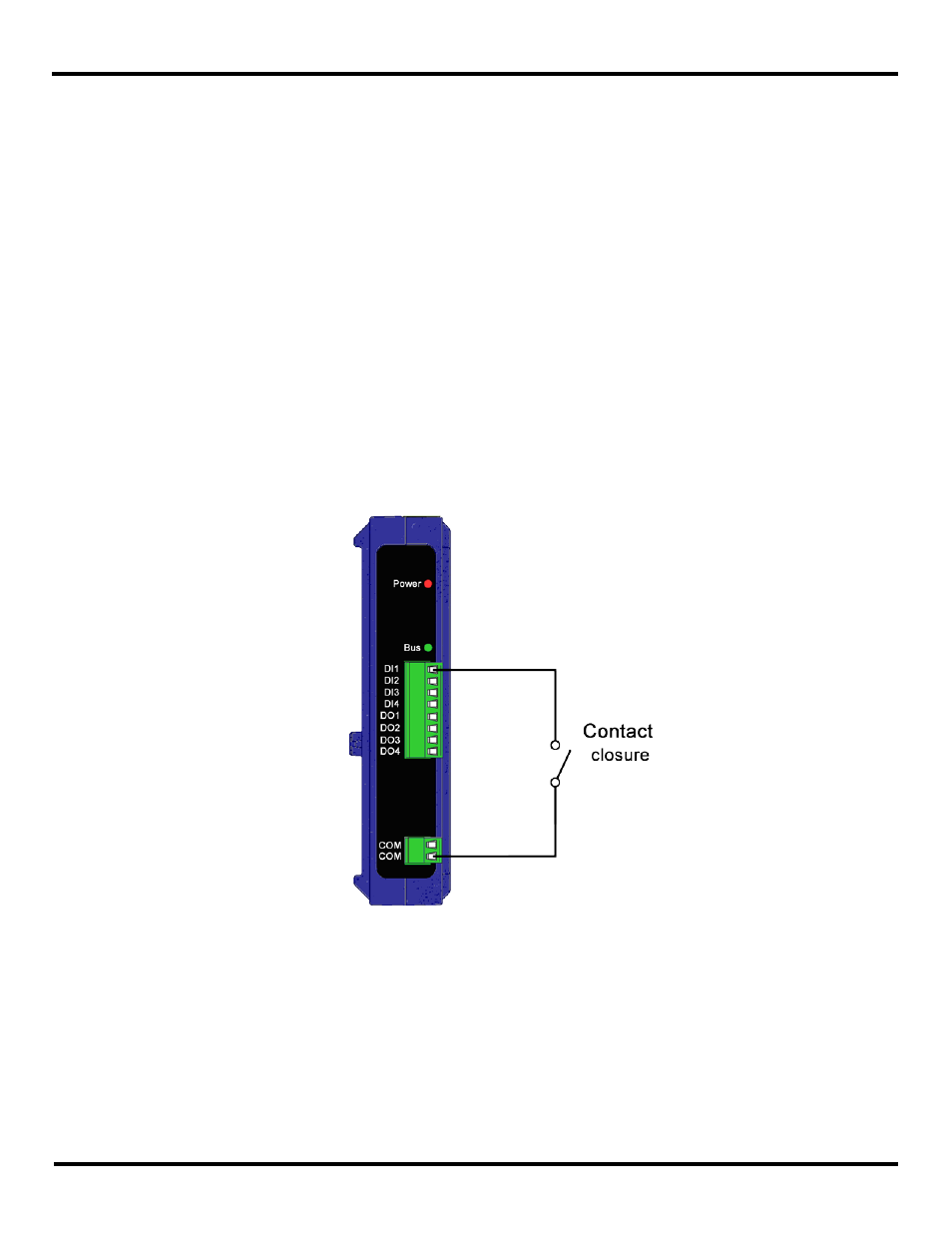
9.1.1 Testing DI
A Digital Input is used to sense a high or low, such as a switch closure. To test the device, on System-1 connect one side of
the switch to the DI on the Zlinx Wireless I/O device and the other side of the switch to ground on the Zlinx Wireless I/O device
(see Figure 45). When the switch is closed the LED on the corresponding DO (assuming it is a sourcing DO) on System-2
should be OFF (low), when the switch is open the LED should be ON (high).
Figure 45 Digital Input wiring