2 peer-to-peer slave, Peer-to-peer slave – B&B Electronics ZZ24D-NA(NB,NC,ND)-SR - Manual User Manual
Page 52
Configuration & Operation
46
Manual Documentation Number: pn7515_ZlinxIO-0712m
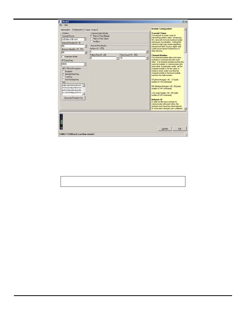
Figure 389 Peer-to-Peer Master Configuration
3. Set the Peer-to-Peer Master address from 1 to 255. Please note the Peer-to-Peer Slave address must also match.
4. The Polling Rate box contains the number of seconds between polls by the Master. The default value of 1 second is
usually satisfactory. The range of values is 0 seconds to 20 seconds. If the I/O points are not updating properly, try
increasing the value.
NOTE: “0” causes the firmware to transfer data as fast as possible with no delays..
5. The Retry Count box contains the number of attempts that will be made to communicate with the Slave device before the
module indicates communication has been lost. Lost communication is indicated by the RF Data and Bus LED’s blinking
alternately. The default value of 10 is usually satisfactory. The range of values is 10 to 255.
5.1.3.2 Peer-to-Peer Slave
To configure the Zlinx Wireless I/O Base Module for Peer-to-Peer Slave Mode:
1. Select the Configuration tab.
2. Select the Peer-to-Peer Slave option button.