5 connecting zlinx wireless i/o to a pc, 6 starting zlinx i/o configuration, Onnecting – B&B Electronics ZZ24D-NA(NB,NC,ND)-SR - Manual User Manual
Page 40: Linx, Ireless, To a, Tarting, Onfiguration
Setup
34
Manual Documentation Number: pn7515_ZlinxIO-0712m
4.5 Connecting Zlinx Wireless I/O to a PC
To connect Zlinx Wireless I/O to a PC:
1. With power disconnected from the Base Module connect any required Expansion Modules to the Base Module. The male
local bus connector on the first Expansion Module plugs into the female connector on the Base Module. The second
Expansion Module plugs into the first, etc.
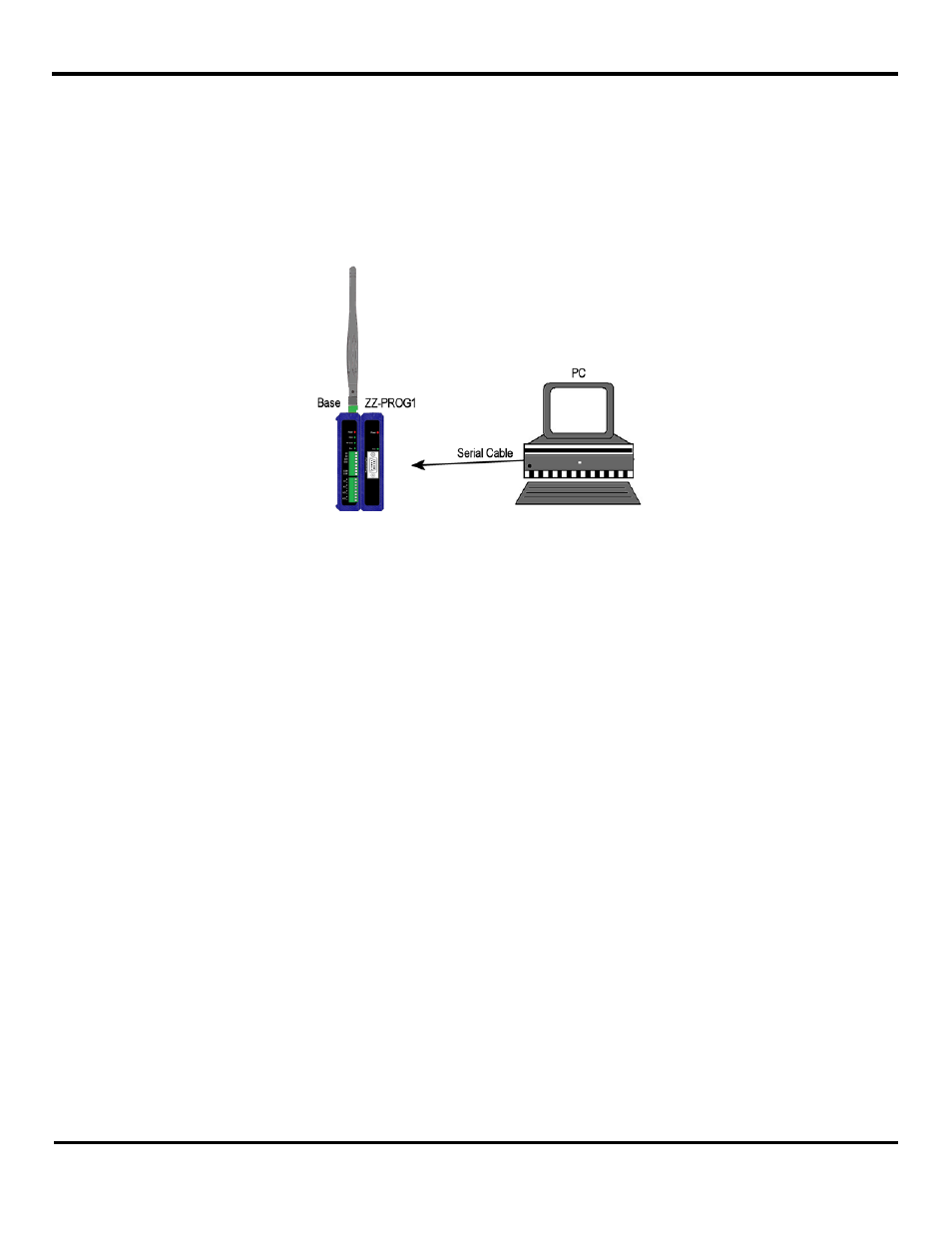
2. With power disconnected from the Base Module, plug the ZZ-PROG1 (or ZZ-PROG1-USB) Configuration Box into the
Base Module.
Figure 31 A PC, Configuration Box and Base Module
3. Connect the PC serial port to the Configuration Box using a straight-through serial (9 pin) cable or USB cable if using the
ZZ-PROG1-USB module.
4. Re-apply power to the Zlinx Wireless I/O Base Module. The Power LED’s should light up.
4.6 Starting Zlinx I/O Configuration
To Start Zlinx Manager:
1. From the Windows Start menu, start the Zlinx Manager software.
Zlinx Manager Screen opens offering navigation to Zlinx Manager or Radio Modem Manager.
2. Click on the Zlinx I/O.
3. To go to the configuration window click on the Zlinx I/O Configuration. Zlinx I/O Firmware Updater, Zlinx I/O Monitor are
also started from this window.
The Zlinx Wireless I/O splash window appears briefly, followed by the discovery window.
4. The Connection drop down list defaults to Automatic discovery. The software scans through COM ports looking for Zlinx
Wireless I/O devices. The scan starts with the most recently used serial port in which a device was found.