3 connectors, 1 antenna connector, 2 power supply connector – B&B Electronics ZZ24D-NA(NB,NC,ND)-SR - Manual User Manual
Page 35: 3 serial port connector, 4 local bus connectors, Connectors, Antenna connector, Power supply connector, Serial port connector, Local bus connectors
Hardware Information
Manual Documentation Number: pn7515_ZlinxIO-0712m
29
3.4.3 Connectors
Zlinx Wireless I/O Base and Expansion Modules feature connectors for connecting field I/O wiring and plugging together Zlinx
Wireless I/O modules (local bus). In addition, Base Modules include connectors for connecting an antenna and power supply.
Configuration Boxes include a serial connector for connecting to a PC COM port or if using the ZZ-PROG1-USB then a USB
connector is provided for connecting to the PC.
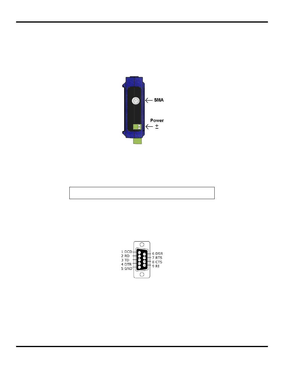
3.4.3.1 Antenna Connector
Base Modules have a reverse SMA antenna connector mounted on the top edge of the enclosure.
Figure 26 Top View of a Base Module
3.4.3.2 Power Supply Connector
The Power Supply connector (Base Modules only) is a two-position removable terminal block located on the top of the unit.
Terminal spacing is 3.5 mm. The terminal block accepts solid and stranded wires from 28 AWG to 16 AWG. Please check
polarity marking in
NOTE: Refer to section 4.1.1 “Power Supply Requirements” for more information.
The Configuration Box and all Expansion Modules receive power from the Base Module via the local bus connector.
3.4.3.3 Serial Port Connector
The Serial Port connector (Configuration Box only) is a DB-9F (female) connector which comes on the ZZ-PROG1. The
Configuration Box is configured as a DCE. For programming, a standard straight-through serial cable with DB-9F on one end
and DB-9M on the other is required. (Part No. 9PAMF6 recommended)
Figure 27 DB-9 Female Serial Port Connector with Pin-out
3.4.3.4 Local Bus Connectors
The Local Bus connectors are included on Base, Expansion, and Configuration Boxes. These connectors are dual row, 14
pin (2 mm spacing) connectors, male on one side of the module and female on the other (except Base Modules which don’t
have left-side connector and Configuration boxes which don’t have right-side connector). Modules are plugged together to
supply power and facilitate communication between modules.
When adding an Expansion Module to a Base Module the male connector on the Expansion Module plugs into the female
connector on the Base Module. The second Expansion Module plugs into the first, and so on, up to a maximum of six
Expansion Modules.