5 exception reporting, Exception reporting – B&B Electronics ZZ24D-NA(NB,NC,ND)-SR - Manual User Manual
Page 56
Configuration & Operation
50
Manual Documentation Number: pn7515_ZlinxIO-0712m
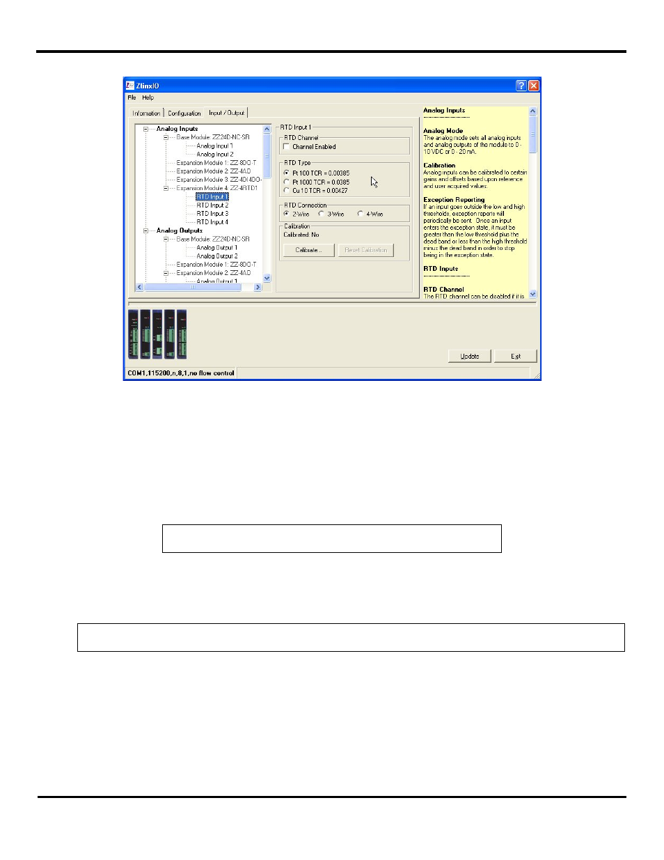
a) An input tree appears listing all Base and Expansion Modules in the system and the inputs available on them.
Figure 45 RTD Input Configuration
b) Select the RTD to be configured.
c) To increase speed, RTD channels may be turned on or off. If nothing is connected to the RTD channel, then uncheck
the Channel Enabled option.
d) Select the RTD type as Pt100, Pt1000, Cu10 depending on your RTD type.
e) Select if you have wired a 2, 3, or 4 wire RTD probe to the input module.
NOTE: Refer to “Appendix F: RTD Module” for more information on RTD module.
5.1.5 Exception Reporting
This feature provides the ability of reporting possible problems on devices. It is applied for both Base and Expansion Modules,
and available only for Modbus mode.
NOTE: Base and only first Expansion Module next to the Base Module can generate an exception.
For Analog Inputs exception reports will be periodically sent if an input goes outside the low and high thresholds. Once an
input enters the exception state, it must be greater than the low threshold plus the dead band or less than the high threshold
minus the dead band in order to stop being in the exception state.
In general, the Modbus protocol does not support exception reporting. In a typical Modbus system the Modbus Master sends
a request to a respective Slave device and the slave device will respond with an ACK. Typical Slave data does not contain I/O
addressing data. Any data sent from the Slave to the Master, without the Master first requesting it, will be ignored by the
Master. Therefore, it’s understood that the exception features will require the end user to use a custom driver to capture the
exception data.