5 rtd wiring, 4 modbus i/o addressing, Rtd wiring – B&B Electronics ZZ24D-NA(NB,NC,ND)-SR - Manual User Manual
Page 31: Modbus i/o addressing
Hardware Information
Manual Documentation Number: pn7515_ZlinxIO-0712m
25
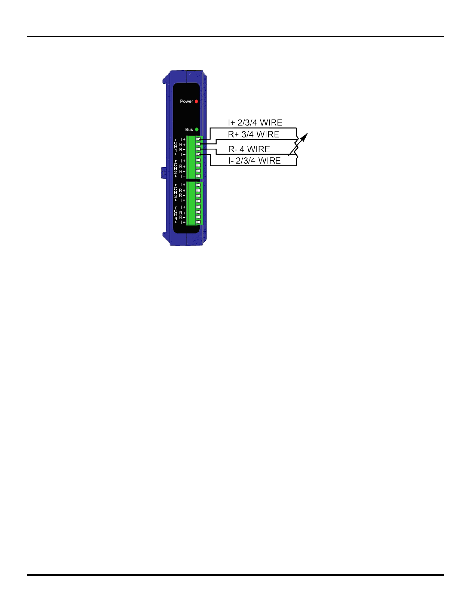
3.3.3.5 RTD Wiring
The following diagram shows typical connection wiring for RTD inputs:
Figure 22 Typical RTD Input Wiring
3.3.4 Modbus I/O Addressing
Zlinx Wireless I/O modules can be configured to operate as wireless Modbus nodes. The Modbus device should be
connected to the Modbus radio modem. In Modbus mode messages are sent across the wireless link from a Modbus radio-
modem to the Zlinx Wireless I/O and from the Zlinx Wireless I/O to the Modbus radio-modem. Digital and Analog Input
information from the Zlinx Wireless I/O inputs is stored in the Zlinx Wireless I/O memory and then sent across the link to the
Modbus modem. Digital and Analog Output information is sent from the Modbus modem to the Zlinx Wireless I/O, stored in its
memory, and then sent to the outputs.
To use Modbus mode successfully, an understanding of the Zlinx Wireless I/O memory map assignments is necessary.
What is a Modbus Map?
A Modbus Map is simply a list for an individual slave device that defines:
What the data is (ex. pressure or temperature readings).
Where the data is stored (which tables and data addresses).
How the data is stored (data types, byte and word ordering).
Some devices are built with a fixed map that is defined by the manufacturer, while other devices allow the operator to
configure or program a custom map to fit their needs.
Modbus function codes supported:
Function 1: Read DO Status
Function 2: Read DI’s
Function 3: Read AO Status
Function 4: Read AI’s
Function 5: Write to Single DO (firmware v2.0 or higher)
Function 6: Write to Single AO
Function 15: Write to Multi DO’s
Messages sent between Zlinx Wireless I/O and a Modbus modem use Modbus memory addresses to specify what type of
information is being sent and where it is stored. In the Modbus addressing scheme each type of I/O (DO, DI, AI, and AO) is
stored in a different section of the memory.