B&B Electronics ZZ24D-NA(NB,NC,ND)-SR - Manual User Manual
Page 63
Configuration & Operation
Manual Documentation Number: pn7515_ZlinxIO-0712m
57
3. With power disconnected from the Base Module connect Expansion Modules requiring updates to the Base Module. The
male local bus connector on the first Expansion Module plugs into the female connector on the Base Module. The second
Expansion Module plugs into the first, etc.
4. With power disconnected from the Base Module, plug the Configuration Box to the right side of the system.
5. Connect the PC serial port (COM 1 to 16) to the Configuration Box using a straight-through serial (9 pin) cable or USB
cable if using the ZZ-PROG1-USB.
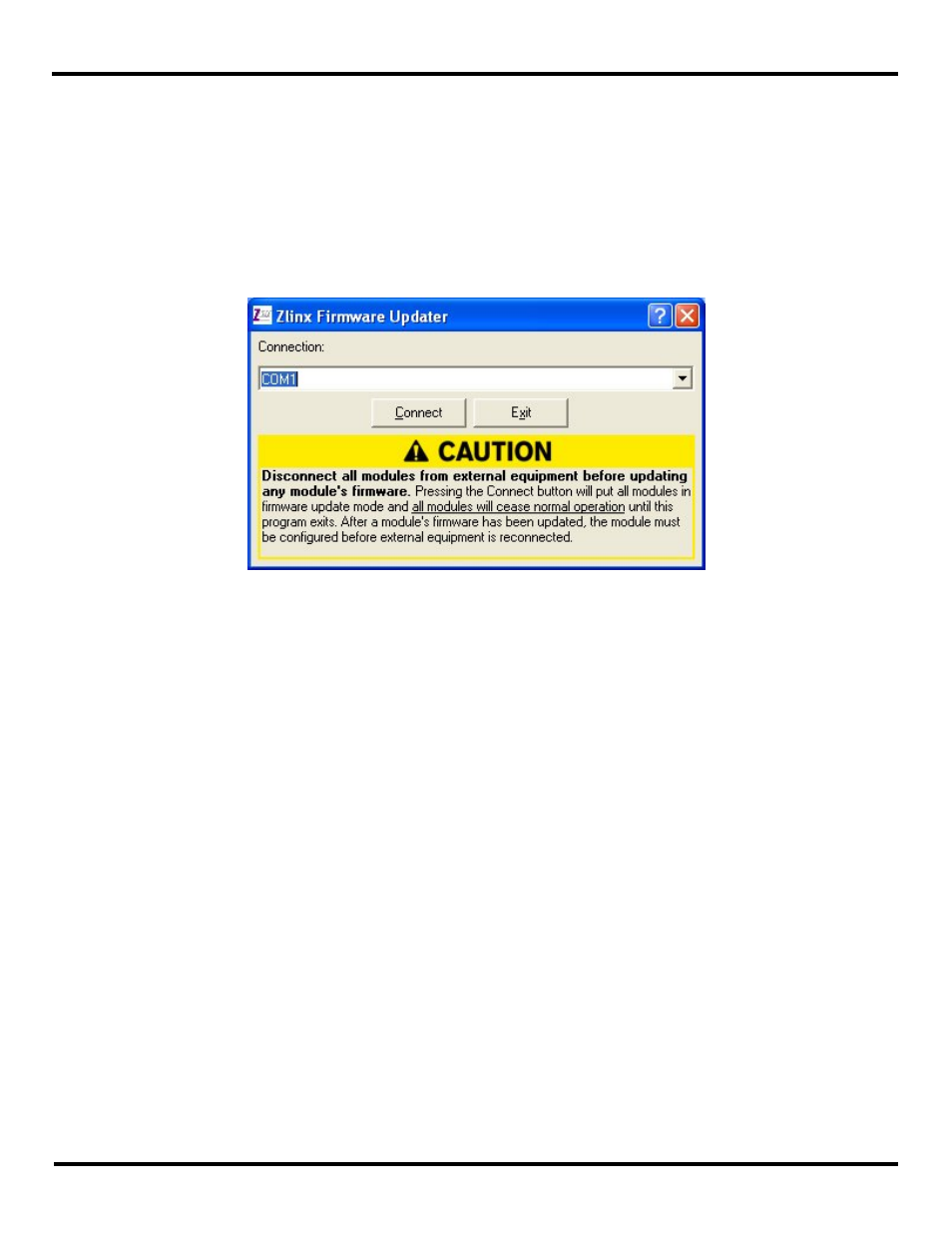
6. From the Windows Start menu, start the Zlinx Manager and choose Zlinx I/O Firmware Updater software.
The Zlinx I/O Firmware Updater Caution dialog box appears.
Figure 44 Firmware Updater Caution Dialog Box
7. Select the COM port from the Connection drop down list.
8. Click Connect.
9. Re-apply power to the Zlinx Wireless I/O Base Module. The Power LED should go on and stay on.
10. The Zlinx I/O Firmware Updater window opens and displays a list of the Base and Expansion Modules.
11. On the module list, select the Base or Expansion Module to be updated.
12. In the Firmware Image drop down box, select the image file (.hex).
13. Click the Program button to load the firmware into the module.
14. Repeat steps 11 to 13 for the other modules in the system.
15. When all updates are complete, click Exit.
16. Before reconnecting the I/O, and before disconnecting the Configuration Box, run the Zlinx Manager software and check
to ensure all modules are configured properly.
17. When the configuration check is complete:
a. Exit the Zlinx Manager program.
b. Disconnect power from the Base Module.
c. Remove the Configuration Box.
d. Reconnect the I/O.