2 testing do with sourcing driver, 3 testing do with sinking driver, Testing do with sourcing driver – B&B Electronics ZZ24D-NA(NB,NC,ND)-SR - Manual User Manual
Page 72: Testing do with sinking driver
Troubleshooting
66
Manual Documentation Number: pn7515_ZlinxIO-0712m
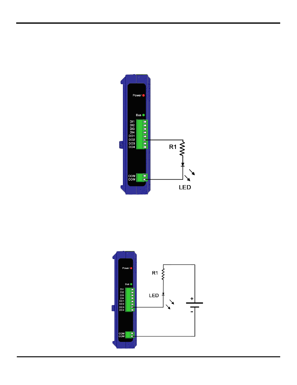
9.1.2 Testing DO with Sourcing Driver
To test a “sourcing” output the following can be performed, remember that a “sourcing” output supplies the voltage itself. See
“Appendix E: Zlinx Wireless I/O Models and Features” to find out which modules are sourcing. On System-1 on the
corresponding Zlinx Wireless I/O device connect an LED between COM and DO, a pull down resistor between the Digital
Output and LED may be required to provide the low voltage condition when the output is turned off (see Figure 46). Make
sure to check the polarity of the LED while connecting it. On System-2 perform contact closure on the corresponding DI,
confirm that the LED on System-1 is OFF with contact closed and ON with contact opened. For a power supply equal to
12VDC connected
to the Base Module use R1=~550 Ω.
Figure 46 Digital Output (Sourcing driver) wiring
9.1.3 Testing DO with Sinking Driver
To test a “sinking” output the following can be performed, remember that a “sinking” output will need a power source. On the
corresponding Zlinx Wireless I/O device of System-1 (see Figure 47) connect an LED between DO and additional power
source as in section 9.1.2. Also connect a resistor ~55
0Ω for a power supply equal to 12VDC connected to the Base Module.
Perform contact closure on the DI side of System-2 and confirm that LED on System-1 is OFF with contact closed and ON with
contact opened.