Expected latency, 1 modbus mode, Odbus – B&B Electronics ZZ24D-NA(NB,NC,ND)-SR - Manual User Manual
Page 65
Expected Latency
Manual Documentation Number: pn7515_ZlinxIO-0712m
59
6
6
.
.
E
E
x
x
p
p
e
e
c
c
t
t
e
e
d
d
L
L
a
a
t
t
e
e
n
n
c
c
y
y
Before you lift a finger towards the perfect wireless installation, think about the impact of wireless communications on your
application. Acceptable bit error rates are many orders of magnitude higher than wired communications. Most radios quietly
handle error detection and retries for you - at the expense of throughput and variable latencies.
Software must be well designed and communication protocols must be tolerant of variable latencies. Not every protocol can
tolerate simply replacing wires with radios. Protocols sensitive to inter-byte delays may require special attention or specific
protocol support from the radio. Do your homework up front to confirm that your software won’t choke, that the intended radio
is friendly towards your protocol, and that your application software can handle it as well.
Assumptions:
No RF retries.
Units were less than 3 feet apart during the testing in a clean RF environment.
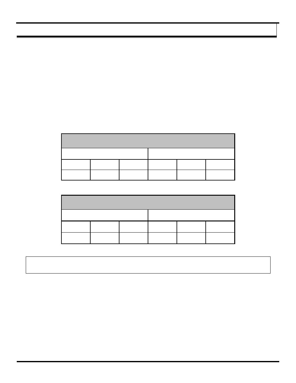
6.1 Modbus Mode
Modbus with 6 Expansion Modules
Reading Inputs
Setting Outputs
SR Base
MR Base
LR Base
SR Base
MR Base
LR Base
40mS
623mS
105mS
16mS
66mS
18mS
Modbus with no Expansion Modules
Reading Inputs
Setting Outputs
SR Base
MR Base
LR Base
SR Base
MR Base
LR Base
15mS
365mS
104mS
8mS
56.2mS
9mS
NOTE: Add 45mS per analog Expansion Module and 25mS per digital Expansion Module. ZZ8D-Nx-LR radios have a 10% duty cycle max
and were not included in the Latency testing.