7 failsafe, 8 communication failure alarm, Failsafe – B&B Electronics ZZ24D-NA(NB,NC,ND)-SR - Manual User Manual
Page 60: Communication failure alarm
Configuration & Operation
54
Manual Documentation Number: pn7515_ZlinxIO-0712m
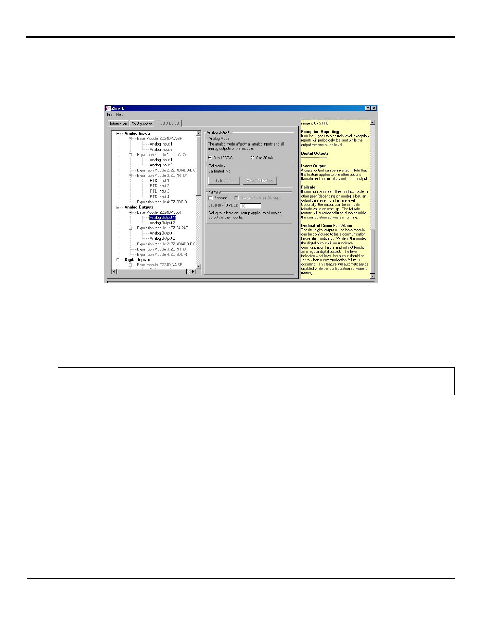
5.1.7 Failsafe
Failsafe mode can be enabled using Zlinx Manager. This feature applies to Base and Expansion Modules. This affects AO’s
and DO’s only. The Failsafe feature allows outputs to go to a user defined level in the event that communication with the
Modbus master (in Modbus mode) or peer (in Peer-to-Peer mode) is lost. The user selects the time frame of communication
failure (see section 5.1.3) and values for all analog and digital output values. When communication failure happens outputs go
to user-defined values. The default setting is disabled.
Figure 4049Window for setting Failsafe command
5.1.8 Communication Failure Alarm
This feature provides an ability to configure DO-1 on the Base Module to be a communication failure alarm indicator. This
feature applies only to Base Modules. While in this mode the Digital Output will only indicate communication failure and will
not function as a regular Digital Output. DO-1 on Base Modules may be turned ON (low) in case of communication failure for
a user-defined period of time (see section 0, 5.1.3).
NOTE: The system will not allow Failsafe and Communication Failure Alarm to be enabled at the same time.
DO-1 will not function as a normal DO when configured to indicate Communication Failure.