B&B Electronics ZZ24D-NA(NB,NC,ND)-SR - Manual User Manual
Page 32
Hardware Information
26
Manual Documentation Number: pn7515_ZlinxIO-0712m
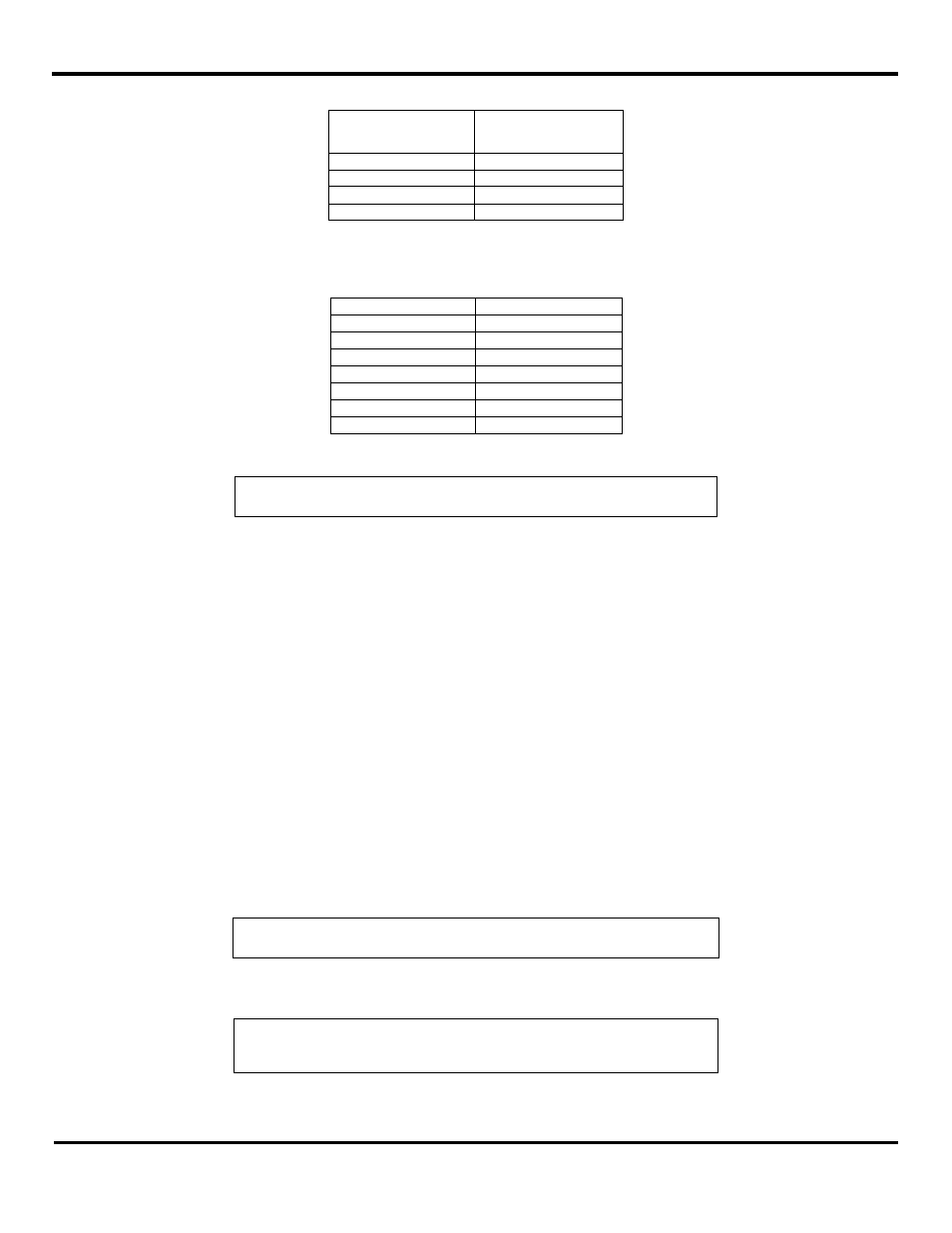
I/O Type
Modbus Memory
Address
DO
00001 to 00112
DI
10001 to 10112
AI
30001 to 30112
AO
40001 to 40112
Figure 23 I/O Memory Areas Table
Within these sections, addresses are reserved for all Zlinx Wireless I/O modules that may be used.
Module
Memory Range
Base
n0001 to n0016
Expansion 1
n0017 to n0032
Expansion 2
n0033 to n0048
Expansion 3
n0049 to n0064
Expansion 4
n0065 to n0080
Expansion 5
n0081 to n0096
Expansion 6
n0097 to n0112
Figure 24 Module I/O Addressing Table
NOTE: In the table “n” is a single digit between 0 and 4.
The following examples show how the addressing works:
Example 1: To turn on the second Digital Output (DO2) on the Base Module, the Modbus modem sends a message placing a
logic 1 in memory location 00002.
Example 2: To cause Expansion Module 3 to output a specified voltage on AO1, the Modbus modem sends a message to set
the register at Modbus address 40049 to the appropriate value. Refer to “Appendix I: Convert Voltage to DAC” for the
information on how to convert voltages to DAC.
A list of all Modbus address assignments for all Zlinx Wireless I/O points is shown in Appendix D: Modbus I/O Assignments”.
Several important points about this list should be noted:
Some addresses are listed but not implemented in current versions of Zlinx Wireless I/O hardware. Refer to
“Appendix D: Modbus I/O Assignments”.
Some addresses are reserved for internal Zlinx Wireless I/O use.
Some addresses are reserved for future use.
40000 series addresses store Analog Output data AND Counter data when Digital Inputs are configured for Counter
operation. For each module, the first eight memory locations are assigned to AO data and the next four locations (7
for Base and 2 for Expansion Modules) are assigned to Counter data.
NOTE: For more information on Counters, see section 3.3.5“Modbus Counters”.
If a Modbus device communicating with Zlinx Wireless I/O tries to send to or receive from a memory address not
implemented by the hardware in use, the Zlinx Wireless I/O replies with an exception response.
NOTE: “Appendix D: Modbus I/O Assignments” of this manual contains a list of
Modbus I/O assignments for the Zlinx Wireless I/O.